Inst ToolsInst ToolsInst Tools
  • Courses
  • Automation
    • PLC
    • Control System
    • Safety System
    • Communication
    • Fire & Gas System
  • Instrumentation
    • Design
    • Pressure
    • Temperature
    • Flow
    • Level
    • Vibration
    • Analyzer
    • Control Valve
    • Switch
    • Calibration
    • Erection & Commissioning
  • Interview
    • Instrumentation
    • Electrical
    • Electronics
    • Practical
  • Q&A
    • Instrumentation
    • Control System
    • Electrical
    • Electronics
    • Analog Electronics
    • Digital Electronics
    • Power Electronics
    • Microprocessor
Search
  • Books
  • Software
  • Projects
  • Process
  • Tools
  • Basics
  • Formula
  • Power Plant
  • Root Cause Analysis
  • Electrical Basics
  • Animation
  • Standards
  • 4-20 mA Course
  • Siemens PLC Course
Reading: Peripheral Inputs and Outputs in Siemens PLC
Share
Notification Show More
Font ResizerAa
Inst ToolsInst Tools
Font ResizerAa
  • Courses
  • Design
  • PLC
  • Interview
  • Control System
Search
  • Courses
  • Automation
    • PLC
    • Control System
    • Safety System
    • Communication
    • Fire & Gas System
  • Instrumentation
    • Design
    • Pressure
    • Temperature
    • Flow
    • Level
    • Vibration
    • Analyzer
    • Control Valve
    • Switch
    • Calibration
    • Erection & Commissioning
  • Interview
    • Instrumentation
    • Electrical
    • Electronics
    • Practical
  • Q&A
    • Instrumentation
    • Control System
    • Electrical
    • Electronics
    • Analog Electronics
    • Digital Electronics
    • Power Electronics
    • Microprocessor
Follow US
All rights reserved. Reproduction in whole or in part without written permission is prohibited.
Inst Tools > Blog > PLC Tutorials > Peripheral Inputs and Outputs in Siemens PLC

Peripheral Inputs and Outputs in Siemens PLC

In this article, we will learn about peripheral inputs and outputs in the Siemens programmable logic controller (PLC).

Last updated: March 4, 2021 11:20 am
Editorial Staff
PLC Tutorials
1 Comment
Share
3 Min Read
SHARE

In this article, we will learn about peripheral inputs and outputs in the Siemens PLC.

In my previous article, I covered the execution of the PLC program and gives an idea of PII and PIQ, which are small storage section in the CPU.

For digital input and output, logic action is stored to PII and PIQ to fasten cycle time.

But, for analog input and output, it directly takes value from the card itself. To recognize addresses of analog input and output, say PLC that not look at PII and PIQ instead, it will look at analog card directly so we need to use a peripheral address.

Peripheral Inputs and Outputs

Before writing any analog address to the programming you must have to add “P” before any analog address you choose.

For Simatic manager software above mentioned addressing method is used to recognize analog signals. For example, PIW100, PID100, PIQ200, etc.

For TIA PORTAL it accepts “P” after and before the address. For example, PIW100 or you can write IW100:P

Let take an example in both Simatic manager and TIA PORTAL to know more about peripheral addresses.

Step 1:

Open TIA PORTAL. Enter into a programming environment.

Now, let see what happened if we do not use a peripheral address.

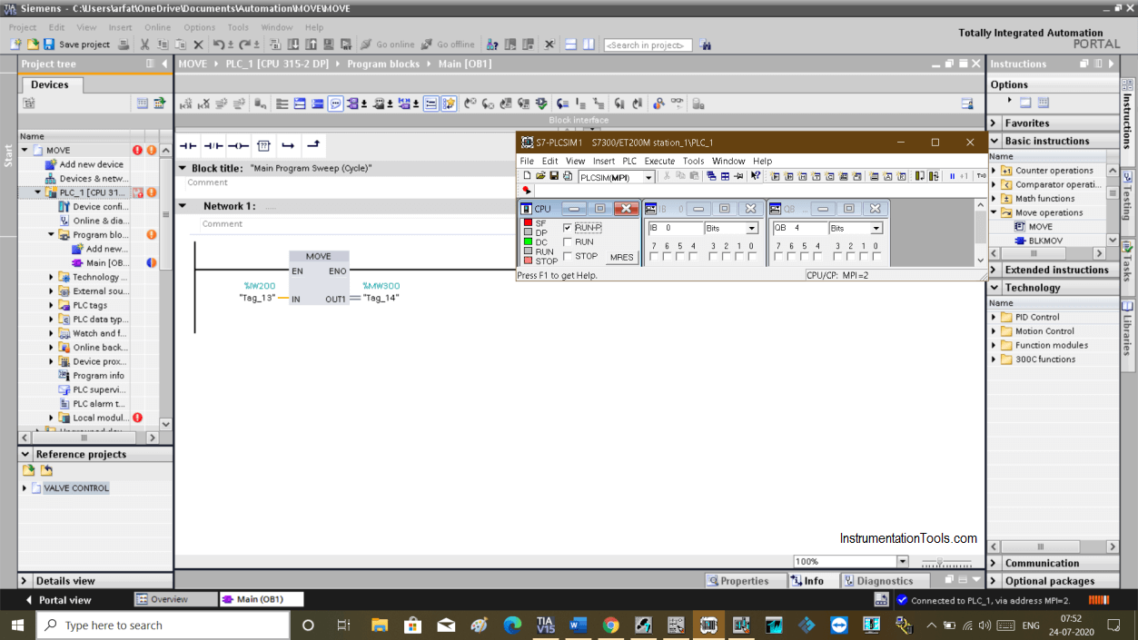
I have added MOVE instruction with an address as you can see in the below window.

If I run a program, an error will occur and CPU goes to STOP mode, which you can see in the below window.

Peripheral Inputs and Outputs in Siemens PLC

Step 2:

To solve this issue we have to use the peripheral address to tell PLC to not look at PII and instead look at the analog cards.

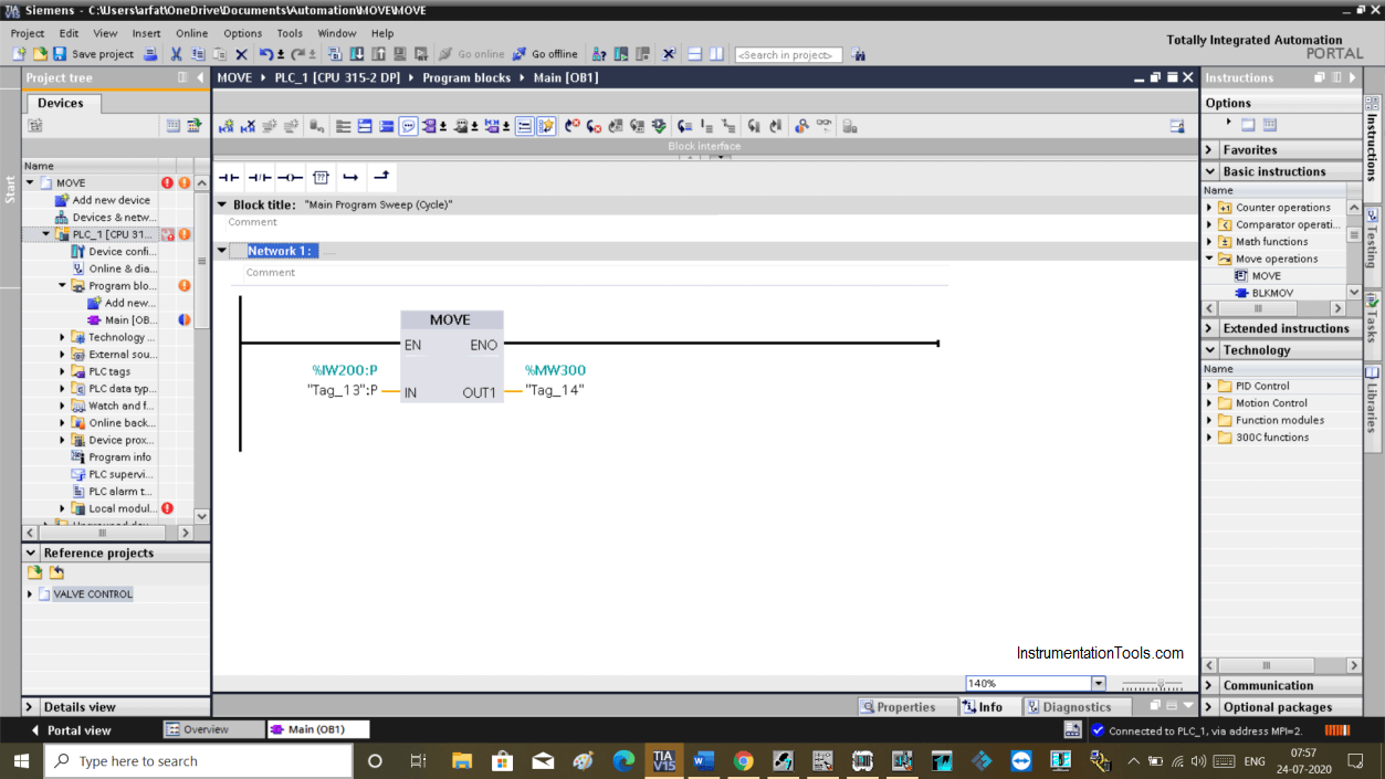
Here, as you can see in the below window that I can use both address PIW and IW:P. Both addresses accept by TIA PORTAL.

If you put PIW as an address, it automatically changes to IW:P as it recognizes that this address belongs to the analog cards.

Siemens Peripheral Address

Step 3:

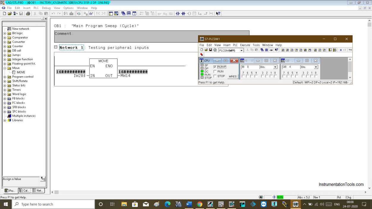
 For Simatic Manager, in the latest version if you won’t put “P” before address it won’t show you an error.

But it is good practice to use the peripheral address for analog addresses.

Siemens S7 PLC Simulator

The same works for analog outputs too.

I hope you may have a clear idea about the use of peripheral addresses in the PLC programming.

Author: Suhel Patel

If you liked this article, then please subscribe to our YouTube Channel for PLC and SCADA video tutorials.

You can also follow us on Facebook and Twitter to receive daily updates.

Read Next:

  • PLC Siemens Training
  • PLC Project Retrieve
  • PLC Program Motor Logic
  • RSLogix 500 PID Function
  • Process Control System
Don't Miss Our Updates
Be the first to get exclusive content straight to your email.
We promise not to spam you. You can unsubscribe at any time.
Invalid email address
You've successfully subscribed !

Continue Reading

Cybersecurity in PLC
SCADA Communication and Protocols
PLC Program using START and STOP Buttons
Establishing a Modbus Driver for SCADA Indusoft Web Studio
Free InTouch SCADA Tutorial Course for Beginners
Connect to the Siemens S7 PLC
Share This Article
Facebook Whatsapp Whatsapp LinkedIn Copy Link
Share
1 Comment
  • EAO says:
    April 21, 2025 at 12:15 pm

    I saw a P&ID using the symbol PIW instead of AI for I/O. Why use PIW Peripheral Input Word (PIW) instead of Analog Input (AI)

    Reply

Leave a Reply Cancel reply

Your email address will not be published. Required fields are marked *

Stay Connected

128.3kFollowersLike
69.1kFollowersFollow
208kSubscribersSubscribe
38kFollowersFollow

Categories

Explore More

What is a Data Block? Global Data Blocks in PLC
Product Sticker Machine with Weighing PLC Program
100 PLC Quiz Questions : True or False
InTouch SCADA Login Password Security
SCADA Engineer Job Responsibilities and Skills
Redundant Automation Systems – Need and Advantages
PLC Programming for Baking with Auto and Manual Modes
What is SCADA ? How does SCADA Works ?

Keep Learning

Retro-Reflective Sensor

What is a Retro-Reflective Sensor? – Principle, Applications

Analog Measurement using Ladder Logic

Analog Measurement using Ladder Logic

LED Indications on PLC

Getting to Know the LED Indications on GE Make PLC

PLC Conversion Program

How to use Converters in PLC

SCADA and PLC Configuration

Examples of SCADA and PLC Configuration Systems

A typical wiring diagram from Field Transmitter to Control Room

How to Wire a Field instrument to Control Room with Example

Simulator in S7-1200 and S7-1500 PLC

How to Work With Simulator in S7-1200 and S7-1500 PLC?

Overview of Industrial Control Systems

Overview of Industrial Control Systems

Learn More

Loop-powered 4-20 mA transmitter

Loop-powered 4-20 mA Transmitter Circuit Voltage drop

Zener Diode Limiter Working

Zener Diode Limiter

Instrument Linearity Error

Instrument Errors – Zero, Span, Linearity

List of 100 Industrial Instrumentation Questions

List of 300 Industrial Instrumentation Questions

Electrical Machines Objective Questions

Electrical Machines MCQ Series 5

Field Instruments Questions and Answers

Control Room and Field Instruments Questions and Answers

Flapper nozzle system

What is Flapper Nozzle System ?

Auto Cane Feed Control System using DCS

Auto Cane Feed Control System using DCS – Sugar Factory

Follow US
All rights reserved. Reproduction in whole or in part without written permission is prohibited.
Welcome Back!

Sign in to your account

Username or Email Address
Password

Lost your password?