Extended Timer logic using Timer and Counter in PLC
In process industries where we deal with many processes in which some of the processes run based on the timer. Some require less time to run and other processes require a longer time.
Processes with smaller timing don’t have an issue but, the processes which require longer times have the issue, especially with Siemens PLCs. The default Siemens PLC timers capable of maximum timing is 2 hours 46 minutes.
If we need more timing functionality in our complex process control logic then we have to create a custom timer block that will handle higher timings than the default system provided value.
In this article, we will be discussing the extensive timer logic using the PLC program.
Let’s consider an example of a pump that needs to run for four straight hours. We will be using two inputs and a pump as an output.
Inputs and Outputs
Inputs: 1. START (I0.0), 2. STOP (I0.1)
Output: 1. PUMP (Q0.0)
Timer: TO
Counter: C0
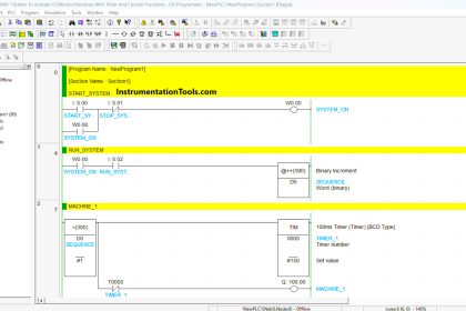
Extended Timer Logic in PLC
We are using here a timer and counter to run the pump for four straight hours. For this, we need a timer to run for 2 hours and a counter to count up to 2 times. Here timer provides the timing value and counter provides the number of times the timer has to run. So, 2 hours x 2 times = 4 hours.
If we need more timing hours means we have to simply change the value of the timer and counter respectively.

Logic Description
When the START button is pressed, which will set the SR flip-flop output then the signal will pass through a timer (S_PEXT). This timer will stay active for a time interval defined by the user.
After timer, a negative edge trigger is used (N_TRIG) which will only energize when the timer goes from true state to false.
The timer stops timing, due to the negative edge gets triggered the counter will energize and the pump will ON till 2 hours as we have selected 2 hours in the timer. (in timer’s first iteration).
We have used NC contact of N_TRIG in between flip-flop and timer. When the counter counts 1 and timer start again timing and will continue for another 2 hours, that makes 4 hours of pump run.
When timer finished timing due to the negative edge it will energize counter again and will count 2.
Now as you can see in the reset of a flip-flop, the comparator is used which is set to 2 and compare it with counter’s cv value MW2. So, when the counter reaches 2 it will activate compare instruction which then passes through the P_TRIG which only allows the signal to pass only once in a cycle.
Now in the same way with NC contact of the pump is used because when timer logic completes it’s 4 hours of counting, the pump will get off and due to NC contact, it will reset SR flip-flop.
For the reset of the counter, the same concept is used. When the counter reaches counts of 2 then signal pass through P_TRIG and reset the counter.
In the last rung, a START button added with SR flip-flop so when you press START button it will set the pump and timer also start timing with it. After 4 hours the pump automatically de-energize due to the compare instruction which will compare with the counter, in our case it is 2.
STOP button is used to stop the whole process.
Author: Suhel Patel
If you liked this article, then please subscribe to our YouTube Channel for PLC and SCADA video tutorials.
You can also follow us on Facebook and Twitter to receive daily updates.
Read Next:
- Troubleshoot PLC Program
- Lube Oil Pump Logic
- PLC Maths Instructions
- Pulse Generation using Timer
- Liquid Mixing PLC Logic


Hello,
I don’t understand you. Explain clearly. Its all confusing.
Hello
Yes because it bit lengthy and you have read properly and follow each rung with program description. Try this program in your software and then read description properly. I hope you will get it then.
In order to understand it properly you have to write this program in your software and follow it, otherwise by only reading the logic doesn’t make you understand it.