Inst ToolsInst ToolsInst Tools
  • Courses
  • Automation
    • PLC
    • Control System
    • Safety System
    • Communication
    • Fire & Gas System
  • Instrumentation
    • Design
    • Pressure
    • Temperature
    • Flow
    • Level
    • Vibration
    • Analyzer
    • Control Valve
    • Switch
    • Calibration
    • Erection & Commissioning
  • Interview
    • Instrumentation
    • Electrical
    • Electronics
    • Practical
  • Q&A
    • Instrumentation
    • Control System
    • Electrical
    • Electronics
    • Analog Electronics
    • Digital Electronics
    • Power Electronics
    • Microprocessor
  • Request
Search
  • Books
  • Software
  • Projects
  • Process
  • Tools
  • Basics
  • Formula
  • Power Plant
  • Root Cause Analysis
  • Electrical Basics
  • Animation
  • Standards
  • 4-20 mA Course
  • Siemens PLC Course
Reading: What is a Annunciator Panel?
Share
Font ResizerAa
Inst ToolsInst Tools
Font ResizerAa
  • Courses
  • Design
  • PLC
  • Interview
  • Control System
Search
  • Courses
  • Automation
    • PLC
    • Control System
    • Safety System
    • Communication
    • Fire & Gas System
  • Instrumentation
    • Design
    • Pressure
    • Temperature
    • Flow
    • Level
    • Vibration
    • Analyzer
    • Control Valve
    • Switch
    • Calibration
    • Erection & Commissioning
  • Interview
    • Instrumentation
    • Electrical
    • Electronics
    • Practical
  • Q&A
    • Instrumentation
    • Control System
    • Electrical
    • Electronics
    • Analog Electronics
    • Digital Electronics
    • Power Electronics
    • Microprocessor
  • Request
Follow US
All rights reserved. Reproduction in whole or in part without written permission is prohibited.
Inst Tools > Blog > Control Systems > What is a Annunciator Panel?

What is a Annunciator Panel?

Last updated: March 4, 2021 1:06 pm
Editorial Staff
Control Systems PLC Tutorials
No Comments
Share
5 Min Read
SHARE

Annunciator Panel is a device that consists of a number of visible signals such as “flags” or lamps indicating the status of an alarm system or systems.

Contents
Annunciator PanelProcess controlPrincipleAnnunciators vs SCADA alarm systems

Each circuit is usually labeled to identify the location and condition being monitored. In addition to the visible signal, an audible signal is usually associated with the device. When an alarm condition is reported, a signal is indicated visibly, audibly, or both. The visible signal is generally maintained until reset either manually or automatically.

An annunciator panel is a group of lights used as a central indicator of status of equipment or systems in an industrial process, building or other installation.

Usually, the annunciator panel includes a main warning lamp or audible signal to draw the attention of operating personnel to the annunciator panel for abnormal events or condition.

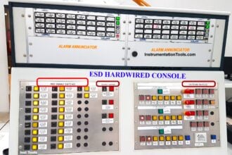
Annunciator Panel
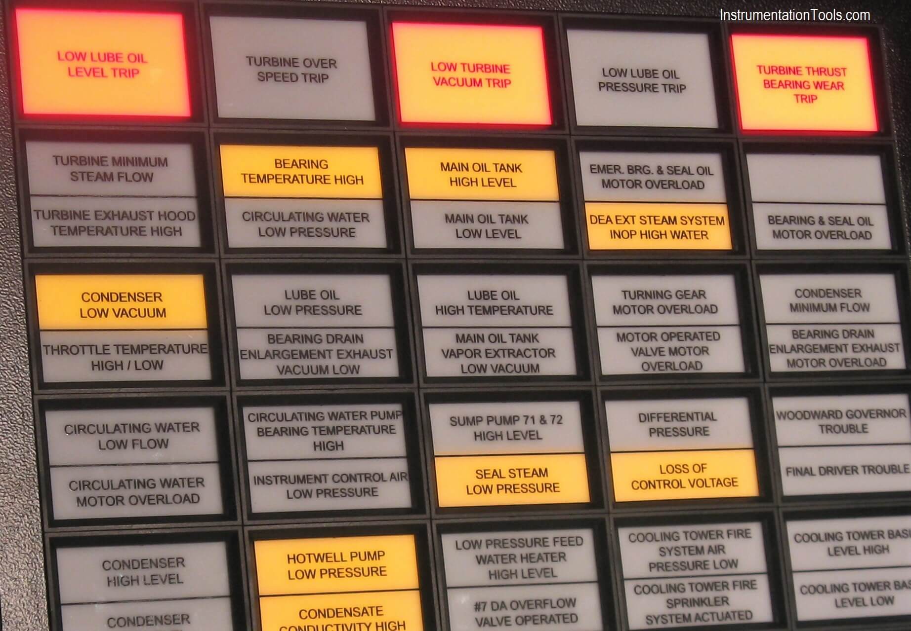
Annunciator Panel

Process control

In industrial process control, an annunciator panel is a system to alert operators of alarm conditions in the plant. Multiple back-lit windows are provided, each engraved with the name of a process alarm.

Lamps in each window are controlled by hard-wired switches in the plant, arranged to operate when a process condition enters an abnormal state (such as high temperature, low pressure, loss of cooling water flow, or many others).

Single point or multipoint alarm logic modules operate the window lights based on a preselected ISA 18.1 or custom sequence. In one common alarm sequence, the light in a window will flash and a bell or horn will sound to attract the operator’s attention when the alarm condition is detected.

The operator can silence the alarm with a button, and the window will remain lit as long as the process is in the alarm state. When the alarm clears (process condition returns to normal), the lamps in the window go out.

Annunciator panels were relatively costly to install in a plant because they had dedicated wiring to the alarm initiating devices in the process plant.

Since incandescent lamps were used, a lamp test button was always provided to allow early detection of failed lamps. Modern electronic distributed control systems usually require less wiring since the process signals can be monitored within the control system, and the engraved windows are replaced by alphanumeric displays on a computer monitor.

Behavior of alarm systems, and colors used to indicate alarms, are standardized. Standards such as ISA 18.1 or EN 60073 simplify purchase of systems and training of operators by giving standard alarm sequences.

Principle

Whenever there is a change of input contacts from Normally Open to Close or from Normally Close to Open position, annunciator changes from rest condition to alarm condition. Hence there is an immediate recognition of fault input which will have a corresponding visual and audio alarm as per the particular selected program sequence.

The base unit of alarm annunciator has four programmable keys for Mute, Acknowledge, Reset & Test function.

  • On pressing the Mute key the internal buzzer can be deactivated.
  • Acknowledge key is used to accept the fault condition,
  • Reset key enables to reset the alarm annunciator to its default state and
  • Test key helps to perform the complete test of the system
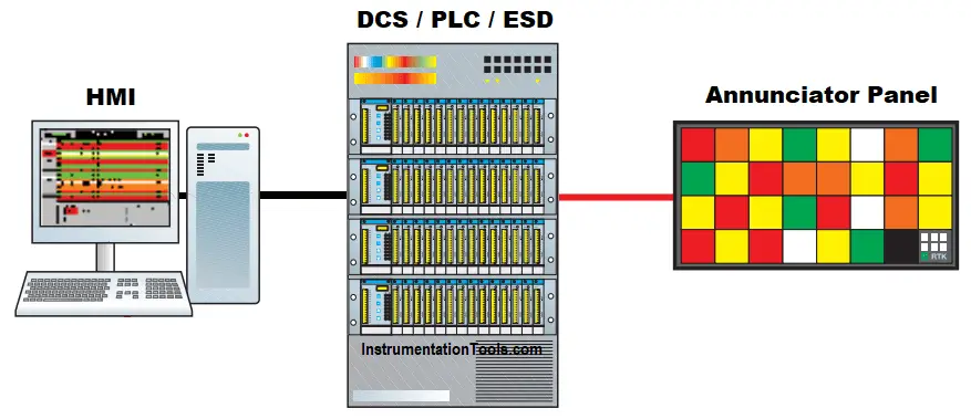
What is an Annunciator

Annunciators vs SCADA alarm systems

SCADA systems were formerly considered the preferred alternative to discrete annunciators. A software-based solution, with almost endless ability to analyze, present and process alarms, has the potential for replacing discrete alarms switches altogether. However, software carries its own reliability risks.

New annunciator panels are utilizing long lasting and bright LEDs that significantly reduce the cost and maintenance of the panels. These new versions of the traditional system are still preferred over computer based systems especially in critical plants like nuclear power generation, oil and gas.

In addition to the above, latest annunciator designs now feature clever electronics to give them very high immunity to noise, and can therefore reduce the amount of false alarms due to noise.

If you liked this article, then please subscribe to our YouTube Channel for PLC and SCADA video tutorials.

You can also follow us on Facebook and Twitter to receive daily updates.

Read Next:

  • Alarms and Trips
  • Industrial Networks
  • Alarm Management System
  • What is a Control Panel?
  • Industrial Automation System
Don't Miss Our Updates
Be the first to get exclusive content straight to your email.
We promise not to spam you. You can unsubscribe at any time.
Invalid email address
You've successfully subscribed !

Continue Reading

Two Hand Press Safety Control Circuit
Various Communication Protocols in PLC
DeltaV System Configuration Changes and Download
Types of Cathodic Protection for Pipeline Protection
Rules for Writing SCL Language in Tia Portal
What is Process Automation? – Simple Automation Example
Share This Article
Facebook Whatsapp Whatsapp LinkedIn Copy Link
Share
Leave a Comment

Leave a Reply Cancel reply

Your email address will not be published. Required fields are marked *

Stay Connected

128.3kFollowersLike
69.1kFollowersFollow
210kSubscribersSubscribe
38kFollowersFollow

Categories

Explore More

Working Principle of Single Phase Preventer Relay
Loop Check of 4-20mA or HART Transmitters
Introduction to Control System
What is Resources Tab in the Siemens PLC?
Flip-Flop PLC Programming: Lights with Adjustable Timers
PID Controller Action : Directing Acting & Reverse Acting
Industrial Automation Mobile Apps
How to Communicate with Excel from Intouch SCADA?

Keep Learning

PLC Fault Diagnosis - PLC Training Documents

PLC Fault Diagnosis – PLC Training Documents

Simatic S7 PLC Backup Steps

How to take Backup from Siemens S7-300 PLC?

STL Programming - SET, RESET, ASSIGN

STL Programming – SET, RESET, ASSIGN

Web SCADA HMI

Web-based SCADA HMI Software

How to Blink Lights in Ladder Logic

How to Blink Lights in Ladder Logic?

Ladder Logic Example of Two Motors

Ladder Logic Example of Two Motors Interlinked with another Motor

Fundamental Motion Control Commands

Fundamental Motion Control Commands

D flip flop in PLC

D Flip Flop PLC Ladder Logic

Learn More

How a Diode Works Animation

How a Gate Works ?

Electrical Machines Questions and Answers

Permanent Magnet DC Motor (PMDC) Questions

SC connector

What is a Network Connector? – Types of Connectors

Transparent Level Gauge

Level Indicators Working Principle

D’Arsonval Movement

D’Arsonval Meter Movement

Motor Feedback Fail Logic in PLC

Motor Feedback Fail Logic in PLC

Innovative Segment Orifice

Pitot-tube Replaced with Innovative Segment Orifice Plate

Emergency Shutdown System

What is Emergency Shutdown System (ESD) ?

Menu

  • About
  • Privacy Policy
  • Copyright

Quick Links

  • Learn PLC
  • Helping Hand
  • Part Time Job

YouTube Subscribe

Follow US
All rights reserved. Reproduction in whole or in part without written permission is prohibited.
Welcome Back!

Sign in to your account

Username or Email Address
Password

Lost your password?