Inst ToolsInst ToolsInst Tools
  • Courses
  • Automation
    • PLC
    • Control System
    • Safety System
    • Communication
    • Fire & Gas System
  • Instrumentation
    • Design
    • Pressure
    • Temperature
    • Flow
    • Level
    • Vibration
    • Analyzer
    • Control Valve
    • Switch
    • Calibration
    • Erection & Commissioning
  • Interview
    • Instrumentation
    • Electrical
    • Electronics
    • Practical
  • Q&A
    • Instrumentation
    • Control System
    • Electrical
    • Electronics
    • Analog Electronics
    • Digital Electronics
    • Power Electronics
    • Microprocessor
Search
  • Books
  • Software
  • Projects
  • Process
  • Tools
  • Basics
  • Formula
  • Power Plant
  • Root Cause Analysis
  • Electrical Basics
  • Animation
  • Standards
  • 4-20 mA Course
  • Siemens PLC Course
Reading: Single Loop Controller Questions
Share
Notification Show More
Font ResizerAa
Inst ToolsInst Tools
Font ResizerAa
  • Courses
  • Design
  • PLC
  • Interview
  • Control System
Search
  • Courses
  • Automation
    • PLC
    • Control System
    • Safety System
    • Communication
    • Fire & Gas System
  • Instrumentation
    • Design
    • Pressure
    • Temperature
    • Flow
    • Level
    • Vibration
    • Analyzer
    • Control Valve
    • Switch
    • Calibration
    • Erection & Commissioning
  • Interview
    • Instrumentation
    • Electrical
    • Electronics
    • Practical
  • Q&A
    • Instrumentation
    • Control System
    • Electrical
    • Electronics
    • Analog Electronics
    • Digital Electronics
    • Power Electronics
    • Microprocessor
Follow US
All rights reserved. Reproduction in whole or in part without written permission is prohibited.
Inst Tools > Blog > Control Systems > Single Loop Controller Questions

Single Loop Controller Questions

Last updated: March 4, 2021 1:12 pm
Editorial Staff
Control Systems PLC Tutorials
1 Comment
Share
3 Min Read
SHARE

A simple diagram is shown here, where a single loop controller controls the speed of a DC electric motor using the concept of feedback control.

Single Loop Controller

Questions on Single Loop Controller

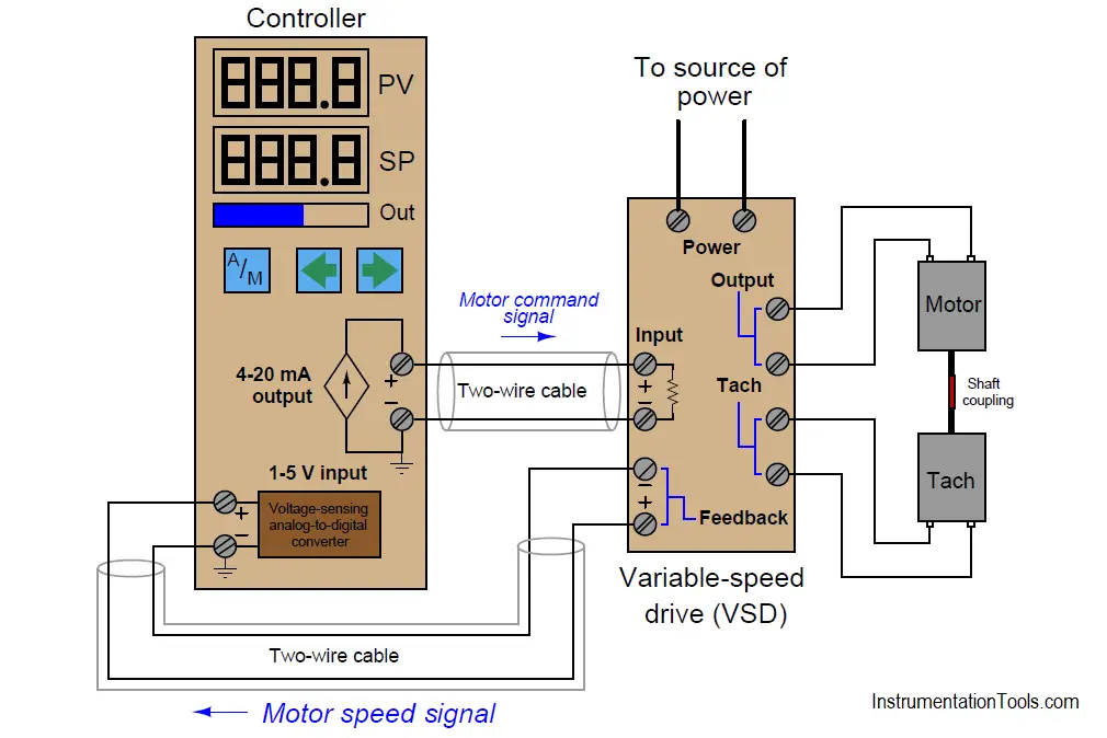
The motor receives its power from the Variable-Speed Drive (VSD), and reports shaft speed to the controller by means of a tachogenerator (“tach”) which generates a DC voltage proportional to shaft speed. The VSD (or VFD) receives the command signal from the loop controller and tries to maintain the motor speed accordingly. Also, the VSD sends the actual motor speed signal back to the loop controller.

Note:

  1. For study purpose, we consider the 12V small motor.
  2. We can replace the single-loop controller with a PID controller in PLC or DCS systems also.

Lets study in the following ways:

Question 1:

If we Place the controller into manual mode and adjust the controller’s output to see how the motor spins (and how its speed is registered on the controller’s process variable display).

Question 2:

If we Place the controller into automatic mode and adjust the controller’s setpoint to see how well the motor speed tracks setpoint. How closely does the motor speed come to being equal with setpoint? How long does it take the motor speed to equalize with setpoint (if it ever does)?

Question 3:

If we Place the controller into manual mode with the motor spinning at approximately 50% speed, then touch the motor shaft with your finger to “load” it down.

Questions 4:

If we Place the controller into automatic mode with the motor spinning at approximately 50% speed, then touch the motor shaft with your finger to “load” it down. How does the automatic-mode response differ from the manual-mode response? In which mode is the motor easiest for you to slow down?

Share Your Answers and Explanations with us.

If you liked this article, then please subscribe to our YouTube Channel for PLC and SCADA video tutorials.

You can also follow us on Facebook and Twitter to receive daily updates.

Read Next:

  • Motor Speed Control using VFD
  • Variable Frequency Drive Principle
  • PID Controller Analysis
  • Closed Loop Control System
  • Instrumentation Technician MCQ
Don't Miss Our Updates
Be the first to get exclusive content straight to your email.
We promise not to spam you. You can unsubscribe at any time.
Invalid email address
You've successfully subscribed !

Continue Reading

How to Prevent Ground Loops in Analog Circuits?
Batch Simulator PLC Example Program using LogixPro Simulator
Design a Water Pump PLC Program using CX-Programmer
Recognizing an Over-Tuned PID Controller by Phase Shift
Check Block Consistency Tools in Simatic Manager
Basics of Wellhead Control Panel (WHCP)
Share This Article
Facebook Whatsapp Whatsapp LinkedIn Copy Link
Share
1 Comment
  • Brown says:
    January 12, 2020 at 6:50 pm

    How to convert field value to engineering value

    Reply

Leave a Reply Cancel reply

Your email address will not be published. Required fields are marked *

Stay Connected

128.3kFollowersLike
69.1kFollowersFollow
210kSubscribersSubscribe
38kFollowersFollow

Categories

Explore More

PLC Programming Example on Multi-Motor Control for Beginners
PLC Program for Fish Feeding System
Stroke Checking Procedure for GCV, SRV, IGV, and LFBV
Actuator Sensor Interface (ASi) Protocol in PLC
Parking Garage Indicator: PLC Automation System
Allen Bradley PLC Subroutines
Manufacturing Execution System (MES) in Industrial Automation
ON Delay Timer using PLC

Keep Learning

Historical Scada graph

Configuration of InTouch Scada Trends

Logic for Always ON and Always OFF bit

Always ON and OFF Bit using Ladder Logic and Statement List

Structured Text PID control loop in PLC

How to Program PID Control in PLC with Structured Text?

Industrial Automation Solution

How to Choose the Right Industrial Automation Solution?

Selector Control Function in DCS

Selector Control Functions

DCS Troubleshooting Control Valve Loop

DCS Troubleshooting Control Valve Loop

Instrumentation Logic Checks

How to Do Logic Checks During Plant Pre-Commissioning

PLC Interlock Example

PLC Interlock Logic with First Input Priority

Learn More

Demo of a SCADA Software – Level Control System

Field Transmitter Installation

Cables and Cable Glands Questions and Answers

Control Valve Parts

Control Valve Parts Questions and Answers

Circuit diagram of Liquid level measurment using Adruino C

Level Measurement and Control using Arduino C

resistor-color-coding-example

IEC labelling for Resistors Color Code

Power Electronics Projects

Top 100 Power Electronics Projects for Engineering Students

PCV

Difference between PCV and PRV

Control Systems Questions & Answers

Control Systems Objective Questions & Answers – Set 6

Menu

  • About
  • Privacy Policy
  • Copyright

Quick Links

  • Learn PLC
  • Helping Hand
  • Part Time Job

YouTube Subscribe

Follow US
All rights reserved. Reproduction in whole or in part without written permission is prohibited.
Welcome Back!

Sign in to your account

Username or Email Address
Password

Lost your password?