Inst ToolsInst ToolsInst Tools
  • Courses
  • Automation
    • PLC
    • Control System
    • Safety System
    • Communication
    • Fire & Gas System
  • Instrumentation
    • Design
    • Pressure
    • Temperature
    • Flow
    • Level
    • Vibration
    • Analyzer
    • Control Valve
    • Switch
    • Calibration
    • Erection & Commissioning
  • Interview
    • Instrumentation
    • Electrical
    • Electronics
    • Practical
  • Q&A
    • Instrumentation
    • Control System
    • Electrical
    • Electronics
    • Analog Electronics
    • Digital Electronics
    • Power Electronics
    • Microprocessor
  • Request
Search
  • Books
  • Software
  • Projects
  • Process
  • Tools
  • Basics
  • Formula
  • Power Plant
  • Root Cause Analysis
  • Electrical Basics
  • Animation
  • Standards
  • 4-20 mA Course
  • Siemens PLC Course
Reading: How Integral Controller Reduces offset error ?
Share
Notification Show More
Font ResizerAa
Inst ToolsInst Tools
Font ResizerAa
  • Courses
  • Design
  • PLC
  • Interview
  • Control System
Search
  • Courses
  • Automation
    • PLC
    • Control System
    • Safety System
    • Communication
    • Fire & Gas System
  • Instrumentation
    • Design
    • Pressure
    • Temperature
    • Flow
    • Level
    • Vibration
    • Analyzer
    • Control Valve
    • Switch
    • Calibration
    • Erection & Commissioning
  • Interview
    • Instrumentation
    • Electrical
    • Electronics
    • Practical
  • Q&A
    • Instrumentation
    • Control System
    • Electrical
    • Electronics
    • Analog Electronics
    • Digital Electronics
    • Power Electronics
    • Microprocessor
  • Request
Follow US
All rights reserved. Reproduction in whole or in part without written permission is prohibited.
Inst Tools > Blog > Control Systems > How Integral Controller Reduces offset error ?

How Integral Controller Reduces offset error ?

Last updated: July 29, 2019 5:30 am
Editorial Staff
Control Systems
No Comments
Share
2 Min Read
SHARE

First we have to know how offset error appears in Proportional controller. Click here to read the article on proportional controller offset error.

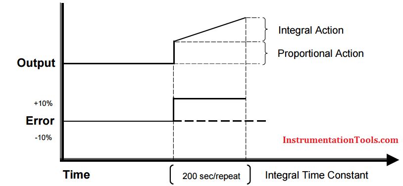
Automatic reset or integral action corrects for any offset between setpoint and process variable automatically by shifting the proportional band over a pre-defined time. The integral time repeats the proportional action over the time set.

Integral redefines the output requirements at the set point until the process variable and set point are equal. Integral engineering units vary by controller manufacturer.

Some use repeats/minute (reset rate), minutes/repeat or seconds/repeat. In Figure below, seconds/repeat is used.

The integral term is added as follows:

Integral controller formula

The smaller the integral number, the proportional action will be repeated more often. If integral is too small, the process variable will oscillate through set point and create erratic control action.

If the number is too large, the action will be sluggish and unable to compensate for process upsets.

Integral controller eliminates offset error

The integral number should be approximately 5 times the dead/lag time of the process variable. If the output is manually changed, dead time is defined as the time required for the process variable to initially react after the change.

The length of time that it takes for the process variable to stabilize at a steady state is lag time.

Example:

40 sec (dead/lag) x 5 = 200 sec/repeat

Articles You May Like :

Reset Control Theory

Tuning Liquid Level Loop

Recognizing PID Controller

PID Tuning Recommendation

Heuristic PID Tuning Procedure
Don't Miss Our Updates
Be the first to get exclusive content straight to your email.
We promise not to spam you. You can unsubscribe at any time.
Invalid email address
You've successfully subscribed !

Continue Reading

Interposing Relay Panel (IRP) – Wiring and Testing Requirements
Process Control Automation PLC Quiz
Compare Modbus, Fieldbus, and Profibus
Instrumentation Engineer Activities & Documents – Detail Design Phase
What is DCS? (Distributed Control System)
Instrumentation and Control (I&C) Design
Share This Article
Facebook Whatsapp Whatsapp LinkedIn Copy Link
Share
Leave a Comment

Leave a Reply Cancel reply

Your email address will not be published. Required fields are marked *

Stay Connected

128.3kFollowersLike
69.1kFollowersFollow
210kSubscribersSubscribe
38kFollowersFollow

Categories

Explore More

Instrumentation Engineer in Process Plant Project
Process Control Instrumentation Glossary
Energize to Safe Loop philosophy
Difference between Fieldbus, Profibus and HART Protocols
Centrifugal Compressor Start Permissive and Interlocks
Vendor View of Supplying Industrial Process Control & Safety Systems
Design Process Graphics in Factory Talk View Studio with an Analog Input
Single Element Drum Level Control System

Keep Learning

Temperature Control System Example

Chemical Reactor Temperature Control System

IACS Network

Remote Connectivity to Industrial Automation Systems

Difference Between SCADA and HMI

Difference Between SCADA and HMI

Process Override Switch

What is Process Override Switch (POS)?

Control Valve Split Range Example - 2

Control Valve Split Range Example

Enterprise Resource Planning in Industrial Automation

What is ERP in Industrial Automation? – Enterprise Resource Planning

Integral Control Principle

Integral Controller Principle

What is Energy Monitoring System

What is Energy Monitoring System ?

Learn More

compressor emergency shutdown system

Compressor Emergency Shutdown Root Cause Analysis

Digital Electronics Objective Questions

Digital Electronics Objective Questions

Top 10 Facts about HART Technology

Top 10 Facts about HART Technology

Modern Instrumentation and Control Systems

Migrate From Obsolete to Modern Instrumentation and Control Systems

Paddle Type Level Switch

What is a Level Switch? Types of Level Switches

Sorting and Counting Products on Conveyors by Color

PLC Programming for Multi-Color Sorting Conveyor System

Industrial Flame Detectors

Industrial Flame Detectors

simple motor start-stop circuit

Liquid Level Switch Control Logic

Menu

  • About
  • Privacy Policy
  • Copyright

Quick Links

  • Learn PLC
  • Helping Hand
  • Part Time Job

YouTube Subscribe

Follow US
All rights reserved. Reproduction in whole or in part without written permission is prohibited.
Welcome Back!

Sign in to your account

Username or Email Address
Password

Lost your password?