Inst ToolsInst ToolsInst Tools
  • Courses
  • Videos
  • Q & A
    • Interview
      • Instrumentation
      • Electronics
      • Electrical
      • Practical Questions
    • MCQ
      • Instrumentation MCQ
      • Electrical MCQ
      • Electronics MCQ
      • Control Systems MCQ
      • Analog Electronics MCQ
      • Digital Electronics MCQ
      • Power Electronics MCQ
      • Microprocessor MCQ
      • Multiple Choice Questions
  • EE
    • Electronics
      • Electronics Q & A
      • Electronic Basics
      • Electronic Devices & Circuits
      • Electronics Animation
      • Digital Electronics
    • Electrical
      • Electrical Basics
      • Electrical Q & A
      • Power Electronics
      • Electrical Machines
      • Electrical Animation
      • Power Systems
      • Switchgear & Protection
      • Transmission & Distribution
  • Measure
    • Control Valves
    • Calibration
    • Temperature
    • Pressure
    • Flow
    • Level
    • Analyzers
    • Switches
    • Vibration
    • Solenoid Valve
  • Control
    • PLC Tutorials
    • Control Systems
    • Safety Instrumented System (SIS)
    • Communication
    • Fire & Gas System
  • More
    • Design
    • Tools
    • Animation
    • Basics
    • Formulas
    • Standards
    • TextBooks
    • Common
    • Software
    • Excel Tools
    • Erection & Commissioning
    • Process Fundamentals
    • Videos
    • Books
Search
All rights reserved. Reproduction in whole or in part without written permission is prohibited.
Reading: Why Offset in Proportional Controller ?
Share
Notification Show More
Font ResizerAa
Inst ToolsInst Tools
Font ResizerAa
  • Courses
  • PLC Tutorials
  • Control Systems
Search
  • Courses
  • Videos
  • Q & A
    • Interview
    • MCQ
  • EE
    • Electronics
    • Electrical
  • Measure
    • Control Valves
    • Calibration
    • Temperature
    • Pressure
    • Flow
    • Level
    • Analyzers
    • Switches
    • Vibration
    • Solenoid Valve
  • Control
    • PLC Tutorials
    • Control Systems
    • Safety Instrumented System (SIS)
    • Communication
    • Fire & Gas System
  • More
    • Design
    • Tools
    • Animation
    • Basics
    • Formulas
    • Standards
    • TextBooks
    • Common
    • Software
    • Excel Tools
    • Erection & Commissioning
    • Process Fundamentals
    • Videos
    • Books
Follow US
All rights reserved. Reproduction in whole or in part without written permission is prohibited.
Inst Tools > Blog > Control Systems > Why Offset in Proportional Controller ?

Why Offset in Proportional Controller ?

Last updated: November 20, 2018 9:41 pm
Editorial Staff
Control Systems
2 Comments
Share
3 Min Read
SHARE

Proportional controller: With proportional band, the controller output changes in “proportion” to the error between process variable and set point. The amplitude of the change is adjustable from 1% to 999.9%. This range may differ from vendor to vendor.

Proportional Band

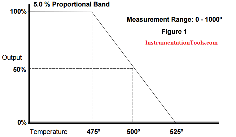
Refer to Figure 1 below. The example of a temperature controller shows a proportional band setting of 5%.

Proportional Band example

Set point = 500°
Measurement range = 0-1000°
5% PB = 5% of 1000° = 50°
100% output at 475° (2.5% of 1000°)
0% output at 525° (2.5% of 1000°)

If the process variable equals the set point (500°), there is a 50% output. As the temperature decreases, the proportional band increases the output linearly toward 100% as the temperature falls toward 475°. The output decreases below 50% as the temperature rises toward 525°.

In this example, a small change in temperature provides a large change in output. If the setting is too small for the process dynamics, oscillations will occur and will not settle at set point. A large PB setting makes the controller act sluggish and will not respond adequately to upsets.

Since proportional control does not incorporate the time that the error has existed, there will always be an offset from set point.

Typically, flow or pressure controllers have a much larger proportional setting due to a possible narrower measurement range and fast process reaction to a change in the control output.

OFFSET

Whenever a process load change occurs and makes the process deviate from the steady state condition, the controller will respond and limit the excursion of the controlled variable.

For this to occur, and error must develop, because, for the controller output (CO) to be at a value other than the bias (b), there must be an error, and so, if the load change continues, so will the error.

This sustained error due to the existence of a continuing process load change in a process controlled by a proportional only controller is termed offset.

Control systems may also experience changes in setpoint, which are called setpoint load changes. Integrating and nonintegrating processes respond differently to these setpoint load changes under proportional control.

Non-integrating processes will experience offsets due to setpoint lead changes while integrating processes will not.

Integral controller will be used to reduce this offset error. click here to the article.
Don't Miss Our Updates
Be the first to get exclusive content straight to your email.
We promise not to spam you. You can unsubscribe at any time.
Invalid email address
You've successfully subscribed !

Recommended Articles

Instrumentation and Control (I&C) Design
Liquid Level Control using Flow Loop
Relay Operation, Types, Symbols & Characteristics
Learn about SCADA and HMI Systems
Difference between Fieldbus, Profibus and HART Protocols
Example of Feedback System
Share This Article
Facebook Whatsapp Whatsapp LinkedIn Copy Link
Share
2 Comments
  • Richard (Dick) Caro, CAP, ISA Life Fellow says:
    March 7, 2017 at 3:46 am

    It is a matter of mathematics. When a Proportional-only controller is switched from Manual to Automatic, we would like for the process to not suddenly change – we call that bumpless transfer. Before the operator makes that switch, the control valve was adjusted by the operator to a position that is satisfactory to running the process. The equation for Proportional-only control is:

    M = Kp * (PV-SP) + B
    where: M is the control valve position
    Kp is the Proportional tuning constant
    PV is the process variable
    SP is the setpoint
    B is a bias

    When the switch to Auto occurs, in order for bumpless transfer to occur, the B term will have a value of the control valve position since by definition, SP=PV, or zero error.

    Then, for any other value of PV, there will be an error value, and a new value of M will be calculated, but since the B term was set for the initial conditions, M will not be at the right value for zero error.

    Reply
  • Soumitra Ghosh says:
    March 7, 2017 at 6:59 am

    Proportional controller works purely on existing error signal.So you always need a measurable error signal to generate an effective output signal.Therefore, there will always be an offset exists in control variable. By increasing gain one can reduce the offset,but this also leads to system oscillation.

    Reply

Leave a Reply Cancel reply

Your email address will not be published. Required fields are marked *

Stay Connected

128.3kFollowersLike
69.1kFollowersFollow
208kSubscribersSubscribe
38kFollowersFollow

Categories

Recent Comments

  • William Snyder on Top Non-PLC Certification Courses for Automation Professionals
  • Kamli on Top Free PLC Software
  • Guifty Shimica on Top Non-PLC Certification Courses for Automation Professionals
  • Guifty Shimica on Top Non-PLC Certification Courses for Automation Professionals

Related Articles

Certified Control Systems Technician (CCST) Sample Questions

Certified Control Systems Technician (CCST) Questions

Difference Between Batch Process and Continuous Process

Difference Between Batch Process and Continuous Process

Earthing Calculations

Electrical Earthing Calculations

feed flow transmitter

Flowmeter Control Strategy

Troubleshooting Pump Control Circuit

Troubleshooting Pump Control Circuit

Design Process Control & Safety Systems

Design View of Supplying Process Control and Safety Systems

Industry 4.0 Explained

Industry 4.0 Explained – Industrial Internet of Things

Steady-state process gain

Steady-State Process Gain

More Articles

Calibrating Transmitter System One Seal with suppressed Zero

Calibrating Level Transmitter with Remote Seals

Download Free Robotics Software

Step by Step Guidelines to Download Free Robotics Software

Chromatography Questions & Answers

Liquid Chromatography Questions & Answers

Thermocouples

Important Factors for Thermocouple Selection

Scaling Sensor Output to Engineering Units

Scaling Sensor Output to Engineering Units

Selecting the Proper Failure Mode

How to Select Control Valve Failure Mode

Manometer with two different liquids

Calculate the Height of Glycerine

Installation & Commissioning Tips for Wireless HART Devices

Installation & Commissioning Tips for HART Devices

Follow US
All rights reserved. Reproduction in whole or in part without written permission is prohibited.
Welcome Back!

Sign in to your account

Username or Email Address
Password

Lost your password?