Inst ToolsInst ToolsInst Tools
  • Ask
  • Courses
  • Videos
  • Q & A
    • Interview
      • Instrumentation
      • Electronics
      • Electrical
      • Practical Questions
    • MCQ
      • Instrumentation MCQ
      • Electrical MCQ
      • Electronics MCQ
      • Control Systems MCQ
      • Analog Electronics MCQ
      • Digital Electronics MCQ
      • Power Electronics MCQ
      • Microprocessor MCQ
      • Multiple Choice Questions
  • EE
    • Electronics
      • Electronics Q & A
      • Electronic Basics
      • Electronic Devices & Circuits
      • Electronics Animation
      • Digital Electronics
    • Electrical
      • Electrical Basics
      • Electrical Q & A
      • Power Electronics
      • Electrical Machines
      • Electrical Animation
      • Power Systems
      • Switchgear & Protection
      • Transmission & Distribution
  • Measure
    • Control Valves
    • Calibration
    • Temperature
    • Pressure
    • Flow
    • Level
    • Analyzers
    • Switches
    • Vibration
    • Solenoid Valve
  • Control
    • PLC Tutorials
    • Control Systems
    • Safety Instrumented System (SIS)
    • Communication
    • Fire & Gas System
  • More
    • Design
    • Tools
    • Animation
    • Basics
    • Formulas
    • Standards
    • TextBooks
    • Common
    • Software
    • Excel Tools
    • Erection & Commissioning
    • Process Fundamentals
    • Videos
    • Books
Search
All rights reserved. Reproduction in whole or in part without written permission is prohibited.
Reading: Blast Furnace Panel Modification to Reduce Down Time by 60 to 70%
Share
Notification Show More
Font ResizerAa
Inst ToolsInst Tools
Font ResizerAa
  • Courses
  • PLC Tutorials
  • Control Systems
Search
  • Ask
  • Courses
  • Videos
  • Q & A
    • Interview
    • MCQ
  • EE
    • Electronics
    • Electrical
  • Measure
    • Control Valves
    • Calibration
    • Temperature
    • Pressure
    • Flow
    • Level
    • Analyzers
    • Switches
    • Vibration
    • Solenoid Valve
  • Control
    • PLC Tutorials
    • Control Systems
    • Safety Instrumented System (SIS)
    • Communication
    • Fire & Gas System
  • More
    • Design
    • Tools
    • Animation
    • Basics
    • Formulas
    • Standards
    • TextBooks
    • Common
    • Software
    • Excel Tools
    • Erection & Commissioning
    • Process Fundamentals
    • Videos
    • Books
Follow US
All rights reserved. Reproduction in whole or in part without written permission is prohibited.
Inst Tools > Blog > Guest Articles > Blast Furnace Panel Modification to Reduce Down Time by 60 to 70%

Blast Furnace Panel Modification to Reduce Down Time by 60 to 70%

Last updated: October 4, 2017 9:52 am
Editorial Staff
Guest Articles Instrumentation Design
2 Comments
Share
4 Min Read
SHARE

With the time demand of increasing the efficiency of production facilities to achieve Target, it is required to made the engineering system robust and fool proof .The below  described is used for various systems and subsystems in the industries and are backed up with practical success .The modification is very helpful in achieving the high end target, increased production capacities ,reduction in human effort and make a WIN WIN situation for the both  employees and employers.

Description of system

The blast furnace operations normally using bell operations for charging & employ the services of pneumatic cylinders for operation. These cylinders are operated by pneumatic solenoid valves which are switched on and off by PLC control system. For continuous operations of the furnace, the complete system needs to be healthy.

Standalone  System panel (Existing System)

The available  solenoid valve system are  generally are of  standalone type system where any malfunction/breakdown of solenoid valve will take a long time of say around 30-40 minutes to remove the valve and place a new valve in line. Thus for a huge system like blast furnace the 40 minutes breakdown cost are very high.

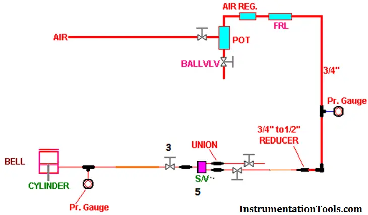
The schematic diagram of the standalone system (Fig 1) is indicated below; in this the solenoid valve S/V 5 is operated as per requirement of furnace. The manual valve 3 is put in open condition. The charging frequency depends on the charging mode of the furnace.

Blast Furnace Panel Modification

Modified panel: (Modified System)

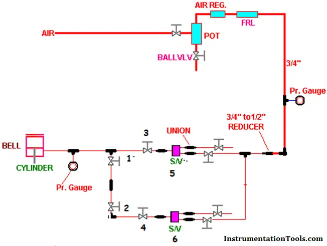
The pneumatic system is little bit modified (Shown below Fig 2) with the putting up of a branch line and the spare solenoid valve as shown in below picture. Here one additional solenoid valve indicated by S/V 6 is placed in system .along with this we have placed simple manual on/off valves indicated by NO 1, 2 and 4.

In normal operation the solenoid S/V 5 remains in working and manual valve 1 is placed in open condition. The manual valves 1, 2 and 4 are in closed position.

Once the things are done ,the breakdown if occurs in the solenoid valve ,the manual valves 3 is  closed .after this manual valves 1,2,& 4 are opened .This facilitates for taking S/V 6  in to system ,simultaneously the coil from the existing solenoid valve S/V 5 is to be placed on the spares solenoid valve ,thus the system is healthy for charging the furnace.

The system can be put back in operation within a span of 10-15 minutes at the most against the normally 30-40 minutes required with a standalone system

Another advantage is that the work is done by only 1 technician in shifts,

Thus the system can help to minimize the downtime of system on account of solenoid valve failure.

Blast Furnace Panel Modification to Reduce Down Time

Article Written by: 

Sh. Pravin V. Maheshkar

Management & technical consultant/trainer  Freelance

Previously Manager –Inst  & Business excellence

(Hindustan zinc ltd ,Echjay steels ltd,total:23 yrs)

Don't Miss Our Updates
Be the first to get exclusive content straight to your email.
We promise not to spam you. You can unsubscribe at any time.
Invalid email address
You've successfully subscribed !
Response Time Test of RTD and Thermocouple
Instrumentation and Control Project Packages – Detail Engineering
Difference Between a Flow Control & a Needle Valve
Why Orifice Flow Meter Flange is Not Recommended 150# Rating?
3 Phase Motor Control using PLC Ladder Logic
Share This Article
Facebook Whatsapp Whatsapp LinkedIn Copy Link
Share
2 Comments
  • Yogesh says:
    February 20, 2016 at 12:54 pm

    I am Regular Reader of this website. Good Article. Thank you Pravin V Maheshkar sir.

    Reply
    • Pravin Maheshkar says:
      February 21, 2016 at 5:29 am

      thanks and my pleasure.If you need any professional help ,I am available on pravinmaheshkar1969@gmail.com

      Reply

Leave a Reply Cancel reply

Your email address will not be published. Required fields are marked *

Stay Connected

128.3kFollowersLike
69.1kFollowersFollow
208kSubscribersSubscribe
38kFollowersFollow

Categories

Recent Comments

  • Kamli on Top Free PLC Software
  • Guifty Shimica on Top Non-PLC Certification Courses for Automation Professionals
  • Guifty Shimica on Top Non-PLC Certification Courses for Automation Professionals
  • MIHARITSOA Aina Sitraka on Top Non-PLC Certification Courses for Automation Professionals

Related Articles

Cable Tray Routing

Cable Routing

Transmitter Range and Sensor Limits

Transmitter Minimum Span, Accuracy & Turndown

Vendor Selection in Procurement Service Cycle (For Industrial Projects)

Compliance Table Application (for Procurement Service Cycle)

Top 10 Facts about HART Technology

Top 10 Facts about HART Technology

sinking-and-sourcing-digital-output-modules

PLC Digital Signals Wiring Techniques

Relay Permissive and interlock circuits

Basics of Permissive and Interlock Circuits

Basics of Thermistors, Thermocouples and RTD's

Basics of Thermistors, Thermocouples and RTD’s

Circular Chart Recorder Calibration Procedure

Circular Chart Recorder Calibration Procedure

More Articles

Allen Bradley SLC 500 PLC Programming

Electrical Machines Questions and Answers

Synchronous Machines Objective Questions

Advantages and Applications of zigzag transformer

Understanding RS-485 Communication

Understanding RS-485 Communication

stepper motors Animation

Fundamentals of DC Motor Animation

Manometer with two different liquids

Calculate the Height of Glycerine

Intrinsic semiconductors

Introduction to Semiconductor Electronics – Types, Materials

Pressure to Current Converter

Pressure to Current (P/I) Converter Principle

Follow US
All rights reserved. Reproduction in whole or in part without written permission is prohibited.
Welcome Back!

Sign in to your account

Username or Email Address
Password

Lost your password?