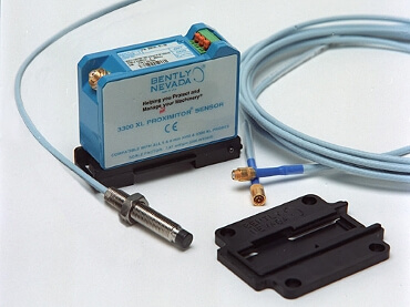
Proximity Transducer System provides an output voltage directly proportional to the distance between the probe tip and the observed conductive surface.
It is capable of both static (position) and dynamic (vibration) measurements, and is primarily used for vibration and position measurement applications on fluid-film bearing machines, as well as Keyphasor and speed measurement applications.
Proximity Transducer System
Proximity Transducer Systems provide an electrical signal that represents the distance between a conductive surface and the probe tip of the system.
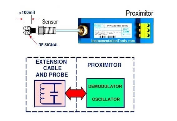
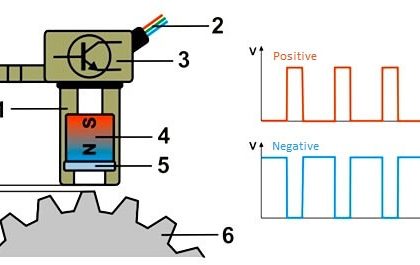
The Proximitor contains electronics that provide two functions:
- Generate a radio frequency (RF) signal using an oscillator circuit.
- Condition the RF signal to extract usable data using a demodulator circuit.
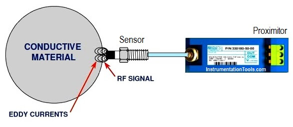
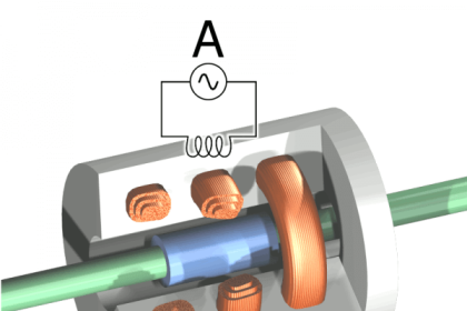
When conductive material is present in the RF field, Eddy Currents flow in the surface of that material.
The penetration depth of the eddy currents depends on the material’s conductivity and permeability. 4140 steel penetration is around 0.003 inches (3 mils).
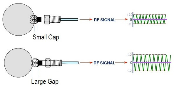
Once the probe is close enough to cause eddy currents to flow in a conductive material the RF signal is affected in two ways:
1. Amplitude is at a MINIMUM when distance (Gap) between probe and target material (Target) is at a MINIMUM. Maximum eddy current flow occurs.
2. Amplitude is at a MAXIMUM when distance (Gap) between probe and target material is at a MAXIMUM. Minimum eddy current flow occurs.
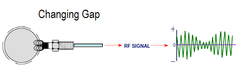
If the target is moving SLOWLY within the RF field, the signal amplitude INCREASES or DECREASES SLOWLY.
If the target is moving RAPIDLY within the RF field, the signal amplitude INCREASES or DECREASES RAPIDLY.
Oscillatory movement of the target causes the RF signal to modulate.
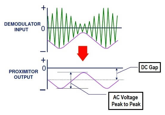
The demodulator circuit deals with slowly or rapidly changing signal amplitude in the same way. If the target is not oscillating, as might be the case with a thrust probe, the Proximitor output is a constant DC voltage, called the gap.
If the target is oscillating (gap changing slowly or rapidly) the Proximitors output is a varying DC voltage (AC) shown above by a sine wave. If the probe is observing a vibration, the Proximitor will provide both a DC (gap) and an AC (vibration) component in the output signal.
A typical system frequency response is from 0 Hz (DC) to 10 kHz. Newer transducer systems, such as the 3300XL proximity system have responses up to 12 kHz.
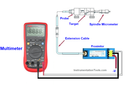
Verification of Proximity Probes
Probe response is verified by measuring and creating a calibration curve.
Problems that can cause proximity probes to be out of tolerance:
- probe cable length
- power supply voltage
- crosstalk and sideview conditions
- target size and material
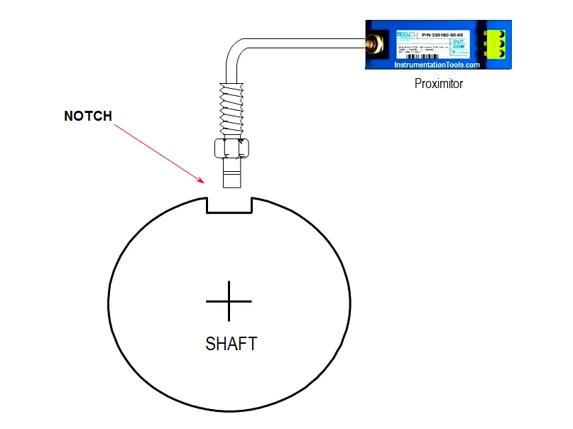
Proximity Probe Used as a Keyphasor
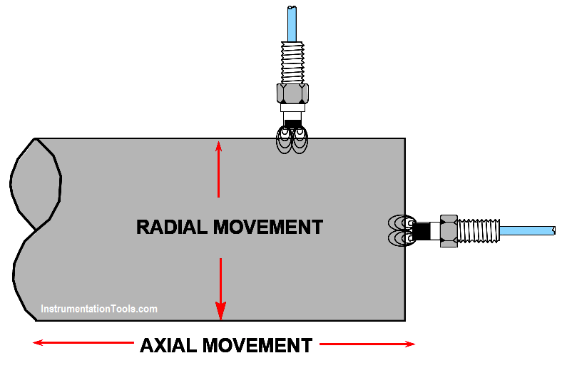
Proximity Probes Installation
Source: Bently Nevada
Articles You May Like :


I am reading this article regarding bently Nevada vibration probe and I have doubt regarding proximitor output.
Suppose my probe is situated in front of rotating shaft in normal operation then it will give DC voltage or AC voltage?
If probe is sense vibration in shaft then what is change in output signal?
In that case output will be AC or DC voltage and if it is AC voltage then what is frequency of that output signal?
So kindly clear my doubts.
Thank You.
Hello Kishan,
The proximitor transducer will always give the output in DC voltage only.
You may be seen the eddy currents in the probe which are oscillating and can be termed as A.C. (in milli volts) but this is nothing but change in signal as per vibration (distance between probe and shaft) and this is connected to proximitor which generates required DC voltage.
We are using 330150 sensor and 330180 a proximitor. The output of combination should give -10 V DC at 1.27 mm but we are getting -10V DC at 0.338 mm.
Why it is happening? We have checked many sensors but giving same.