Inst ToolsInst ToolsInst Tools
  • Courses
  • Videos
  • Q & A
    • Interview
      • Instrumentation
      • Electronics
      • Electrical
      • Practical Questions
    • MCQ
      • Instrumentation MCQ
      • Electrical MCQ
      • Electronics MCQ
      • Control Systems MCQ
      • Analog Electronics MCQ
      • Digital Electronics MCQ
      • Power Electronics MCQ
      • Microprocessor MCQ
      • Multiple Choice Questions
  • EE
    • Electronics
      • Electronics Q & A
      • Electronic Basics
      • Electronic Devices & Circuits
      • Electronics Animation
      • Digital Electronics
    • Electrical
      • Electrical Basics
      • Electrical Q & A
      • Power Electronics
      • Electrical Machines
      • Electrical Animation
      • Power Systems
      • Switchgear & Protection
      • Transmission & Distribution
  • Measure
    • Control Valves
    • Calibration
    • Temperature
    • Pressure
    • Flow
    • Level
    • Analyzers
    • Switches
    • Vibration
    • Solenoid Valve
  • Control
    • PLC Tutorials
    • Control Systems
    • Safety Instrumented System (SIS)
    • Communication
    • Fire & Gas System
  • More
    • Design
    • Tools
    • Animation
    • Basics
    • Formulas
    • Standards
    • TextBooks
    • Common
    • Software
    • Excel Tools
    • Erection & Commissioning
    • Process Fundamentals
    • Videos
    • Books
Search
All rights reserved. Reproduction in whole or in part without written permission is prohibited.
Reading: How to Read Circular Chart Recorder for Flow Measurement?
Share
Notification Show More
Font ResizerAa
Inst ToolsInst Tools
Font ResizerAa
  • Courses
  • PLC Tutorials
  • Control Systems
Search
  • Courses
  • Videos
  • Q & A
    • Interview
    • MCQ
  • EE
    • Electronics
    • Electrical
  • Measure
    • Control Valves
    • Calibration
    • Temperature
    • Pressure
    • Flow
    • Level
    • Analyzers
    • Switches
    • Vibration
    • Solenoid Valve
  • Control
    • PLC Tutorials
    • Control Systems
    • Safety Instrumented System (SIS)
    • Communication
    • Fire & Gas System
  • More
    • Design
    • Tools
    • Animation
    • Basics
    • Formulas
    • Standards
    • TextBooks
    • Common
    • Software
    • Excel Tools
    • Erection & Commissioning
    • Process Fundamentals
    • Videos
    • Books
Follow US
All rights reserved. Reproduction in whole or in part without written permission is prohibited.
Inst Tools > Blog > Flow Measurement > How to Read Circular Chart Recorder for Flow Measurement?

How to Read Circular Chart Recorder for Flow Measurement?

Flow Transmitter output in square-root value and chart recorder prints flow value in range 0 to 100%. How to read circular chart recorder?

Last updated: November 2, 2023 10:23 am
R Jagan Mohan Rao
Flow Measurement
1 Comment
Share
3 Min Read
SHARE

Flow Transmitter output in square-root value and chart recorder prints flow value in the range of 0 to 100%.

Contents
How to Read Circular Chart Recorders?Circular Chart RecorderTypes of ChartsPeriod MethodHow to use and read chart circular chart recorder for flow measurements?

How to Read Circular Chart Recorders?

The simplified formula for the gas flow is

Q = C √ (h P )

Where

Q = Quantity of gas (cu. Ft.) flowing for any given period

C = Coefficient for the same period

h = average differential pressure for that period

P = average absolute static pressure for that period.

Circular Chart Recorder

Please find here below a Circular Chart and method how to read flow measurement.
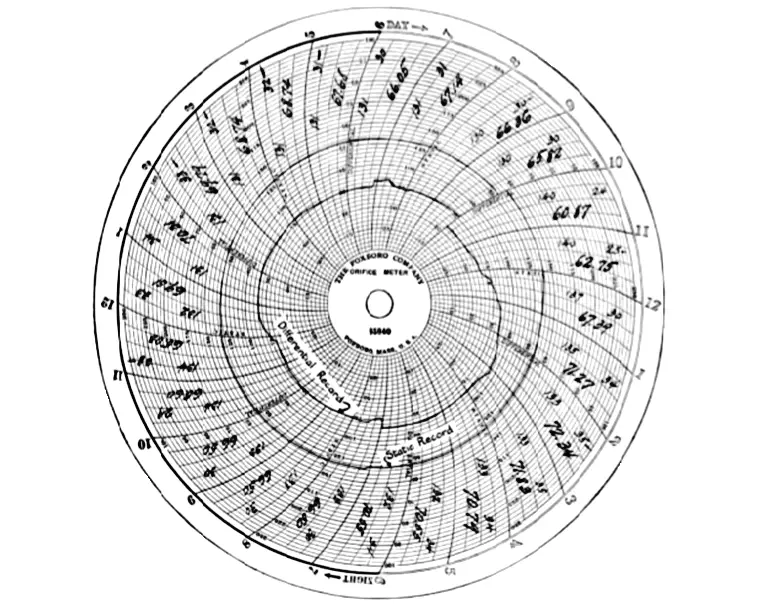
Circular Chart Recorder

Figure 1

The square root of the values of h and P, must be determined as a part of the computation, and reference table as shown below made to facilitate for convenience.

Types of Charts

There are three methods of computing orifice meter charts

  1. The period or inspection method, in which the differential and static pressures are observed for each fifteen minute or hourly period.
  2. The Planimeter method, in which the average differential and static pressures are obtained by means of a radial planimeter.
  3. The integrator method, in which both records are averaged at the same time and the average extension read directly from the dials of an integrating machine.

Period Method

When gas is passing for fully twenty four hour and charts are readable for the entire period.

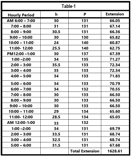
This may be handled in either one of the two ways. The readings for each fifteen minute or hourly period may be set down directly on the chart, together with their corresponding extensions. The extension is the product of the square root of h and P, found in the below table.

Extreme care must be used to see that the differential and static readings are taken for corresponding periods.

The total number of extensions in Figure -1 or Table – 1 is 1628.61 upon rounded to four significant figures, this amount becomes 1629. If this is multiplied by assumed hourly coefficient of 300 gives 488,700 which is daily flow of gas in Cu.Ft.
How to Read Circular Chart Recorder

How to use and read chart circular chart recorder for flow measurements?

  • In a pneumatic flow transmitter, the output will be in square root.
  • Convert square signal to linear by a Square root/Linear extractor.
  • With a Circular recorder chart (range: 0-100%), it is easy to read the flow measurements.

If you liked this article, then please subscribe to our YouTube Channel for Instrumentation, Electrical, PLC, and SCADA video tutorials.

You can also follow us on Facebook and Twitter to receive daily updates.

Read Next:

  • Strip Chart Recorder Principle
  • Orifice Flow Meters Compensation
  • Facts About Orifice Flow Meters
  • Oval Gear Flow Meters Principle
  • Linear to Square Root Extraction
Don't Miss Our Updates
Be the first to get exclusive content straight to your email.
We promise not to spam you. You can unsubscribe at any time.
Invalid email address
You've successfully subscribed !

Recommended Articles

What is a Paddle Wheel Flow Meter?
What is a Torbar? – Averaging Pitot Tubes
Square-Root in DCS or Flow Transmitter?
In-Line Flow Switch Working Principle and Animation
All About Instrumentation Impulse Lines
What is an Orifice Meter?
Share This Article
Facebook Whatsapp Whatsapp LinkedIn Copy Link
Share
1 Comment
  • Breaker says:
    January 18, 2019 at 4:06 am

    thanks for the article but you didn’t mentioned the last tow methodes and how to use them

    Reply

Leave a Reply Cancel reply

Your email address will not be published. Required fields are marked *

Stay Connected

128.3kFollowersLike
69.1kFollowersFollow
208kSubscribersSubscribe
38kFollowersFollow

Categories

Recent Comments

  • William Snyder on Top Non-PLC Certification Courses for Automation Professionals
  • Kamli on Top Free PLC Software
  • Guifty Shimica on Top Non-PLC Certification Courses for Automation Professionals
  • Guifty Shimica on Top Non-PLC Certification Courses for Automation Professionals

Related Articles

Averaging Pitot Tubes

Pitot Tube Problems and Troubleshooting Steps – Flow Instrument

What is an Orifice Flange ?

What is an Orifice Flange? – Purpose and Applications

Flow Meters Troubleshooting

Turbine Flow Meters Troubleshooting

Rotameters Working

Rotameter Working Principle and Animation

Orifice Plate Sizing

Orifice Sizing Guidelines and Thumb Rules with Flowchart

Thermal Dispersion Flow Switch Working Principle

Thermal Dispersion Flow Switch Working Principle

Servo Operated Electro Magnetic Flowmeter Objective Questions

Electro-Magnetic Flow meter Objective Questions

Oval gear Flow Meter Principle

Oval Gear Meter – Principle, Advantages, Limitations, Applications

More Articles

Step and Touch Potential

What Is Step and Touch Potential and Reducing Resistance To Ground?

Reset Logic for pump Run Hours

PLC Program to Count Running Hours of any Equipment

High Voltage and Power System Stability Interview Questions

High Voltage and Power System Stability Interview Questions

annunciator-alarm-simulator

Alarm Simulator for Annunciator Logic

Gas Detection System Abbreviations

Gas Detection System Abbreviations

Bubble Tube Level measurement

Bubble Tube Level Measurement Principle

Weir Diaphragm Valve

Diaphragm Valves Construction, Types, Stem & Bonnet Assembly

Control Valve Direction of Control Action

PID Controller Action : Directing Acting & Reverse Acting

Follow US
All rights reserved. Reproduction in whole or in part without written permission is prohibited.
Welcome Back!

Sign in to your account

Username or Email Address
Password

Lost your password?