Inst ToolsInst ToolsInst Tools
  • Courses
  • Automation
    • PLC
    • Control System
    • Safety System
    • Communication
    • Fire & Gas System
  • Instrumentation
    • Design
    • Pressure
    • Temperature
    • Flow
    • Level
    • Vibration
    • Analyzer
    • Control Valve
    • Switch
    • Calibration
    • Erection & Commissioning
  • Interview
    • Instrumentation
    • Electrical
    • Electronics
    • Practical
  • Q&A
    • Instrumentation
    • Control System
    • Electrical
    • Electronics
    • Analog Electronics
    • Digital Electronics
    • Power Electronics
    • Microprocessor
  • Request
Search
  • Books
  • Software
  • Projects
  • Process
  • Tools
  • Basics
  • Formula
  • Power Plant
  • Root Cause Analysis
  • Electrical Basics
  • Animation
  • Standards
  • 4-20 mA Course
  • Siemens PLC Course
Reading: PLC Temperature Control using Pulse Width Modulation (PWM)
Share
Font ResizerAa
Inst ToolsInst Tools
Font ResizerAa
  • Courses
  • Design
  • PLC
  • Interview
  • Control System
Search
  • Courses
  • Automation
    • PLC
    • Control System
    • Safety System
    • Communication
    • Fire & Gas System
  • Instrumentation
    • Design
    • Pressure
    • Temperature
    • Flow
    • Level
    • Vibration
    • Analyzer
    • Control Valve
    • Switch
    • Calibration
    • Erection & Commissioning
  • Interview
    • Instrumentation
    • Electrical
    • Electronics
    • Practical
  • Q&A
    • Instrumentation
    • Control System
    • Electrical
    • Electronics
    • Analog Electronics
    • Digital Electronics
    • Power Electronics
    • Microprocessor
  • Request
Follow US
All rights reserved. Reproduction in whole or in part without written permission is prohibited.
Inst Tools > Blog > PLC Tutorials > PLC Temperature Control using Pulse Width Modulation (PWM)

PLC Temperature Control using Pulse Width Modulation (PWM)

Last updated: March 4, 2021 4:06 pm
Editorial Staff
PLC Tutorials
1 Comment
Share
4 Min Read
SHARE

Write the PLC program for temperature control with PWM output of PID.

Contents
Temperature control with PWM output of PIDSolutionList of Inputs/OutputsLadder diagram for Temperature control with PWM of PIDProgram Description

Temperature control with PWM output of PID

PLC Temperature Control PWM (Pulse Width Modulation)

Solution

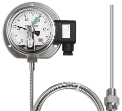
Here we use RTD sensor for temperature measurement and a transmitter to convert sensor output into standard 4-20mA current output, which is then connected to PLC input.

RTD sensor will detect temperature and transmitter will generate signal according to measured temperature.

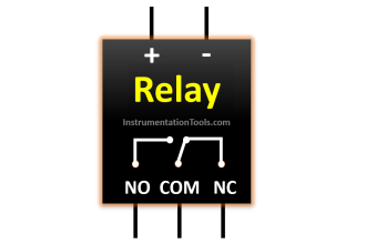
Solid State Relay (SSR) drive is used to control the heater and SSR will be controlled by PWM (pulse width modulation) output of PLC. Solid State Relay Drive will control the heater power supply in-order to maintain the required temperature.

For example, if PLC output PWM varies from range 0 to 100% then accordingly SSR will control the Heater power supply, so we can maintain the heater temperature.

PID controller will generate PWM as per temperature input signal feedback.

List of Inputs/Outputs

List of Inputs

  • Temperature Analog input :- IW64

List of Outputs

  • PWM output for heater (SSR) : Q1.1

M memory

  • PID enable :- M61.0
  • Manual enable :- M61.1
  • PID reset :- M61.2
  • Set temperature :- MD500
  • Actual temperature :- MD704
  • PID output (%) :- MD758
  • PID state word :- MW770
  • PID error word :- MD778
  • PID enable input :- M61.0
  • PID manual mode enable input :- M61.1
  • PID controller reset :- M61.2
  • PID high limit alarm :- M766.0
  • PID low limit alarm:-M766.1
  • PID input warning:-M766.2

Ladder diagram for Temperature control with PWM of PID

PLC Temperature Control PWM
Temperature Control PWM
Temperature control with PWM output of PID

Program Description

For this application we used S7-1200 PLC and TIA portal software for programming.

Network 1 :

In network we configured standard parameters for PID function.

“Drive PID”.sRet.r_Ctrl_Gain:- saved proportional gain or P gain for PID (1.0).

“Drive PID”.sRet.r_Ctrl_Ti:-Saved integral time or I gain for PID (20s).

Network 2 :

“Drive PID”.sRet.r_Ctrl_Td:-Saved derivative time or D gain for PID (0s).

Network 3 :

Here we have taken temperature PID max output limit and minimum output limit. We have considered here max limit for PID output 100 and minimum limit is 0.

Network 4 :

Sampling time of the PID_Compact instruction r_Cycle is determined automatically and usually equivalent to the cycle time of the calling OB.

Consider 0.1s for this application.

Network 5 :

Here we used PID controller which will control the SSR by providing PWM output.

Network 6 :

PID run mode control enabled.

Network 7 :

Here we converted current (4-20mA) input signal into digital (0- 27648) signal.

Note :- Above application may be different from actual application. This example is only for explanation purpose only. We can implement this logic in other PLC also. This is the concept of temperature control with PWM of PID, we can use this concept in other examples also.

All parameters and graphical representations considered in this example are for explanation purpose only, parameters or representation may be different in actual applications. Also all interlocks are not considered in the application.

Author : Bhavesh

If you liked this article, then please subscribe to our YouTube Channel for PLC and SCADA video tutorials.

You can also follow us on Facebook and Twitter to receive daily updates.

Read Next:

Top 100 PLC Objective Questions

PID tuning procedures

Instrumentation Functional diagrams

PLC Analog Input Card Resolution

Programmable Logic Controller Quiz

Don't Miss Our Updates
Be the first to get exclusive content straight to your email.
We promise not to spam you. You can unsubscribe at any time.
Invalid email address
You've successfully subscribed !

Continue Reading

InTouch SCADA Login Password Security
PLC Pneumatic Circuit Control
Tia Portal – OB10 Time of Day Interrupt Organization Block
What is Loop Checking?
PLC based Automatic Packaging System
High-end Programmable Logic Controller – Schneider PLC
Share This Article
Facebook Whatsapp Whatsapp LinkedIn Copy Link
Share
1 Comment
  • KK says:
    March 6, 2019 at 7:33 am

    Give some example of Split range control with PWM output of PID

    Reply

Leave a Reply Cancel reply

Your email address will not be published. Required fields are marked *

Stay Connected

128.3kFollowersLike
69.1kFollowersFollow
210kSubscribersSubscribe
38kFollowersFollow

Categories

Explore More

Real-Time Clock in Omron PLC? – CX Programmer
PLC Problems Troubleshooting
How to Reduce Relay Noise in PLC Systems?
PLC Functional Block Diagram for Logic Gates
PLC Electric Motor Interlocks
What is 21 CFR in SCADA and HMI Systems?
How to take Backup from Siemens S7-300 PLC?
Establishing a Modbus Driver for SCADA Indusoft Web Studio

Keep Learning

Draw a Ladder Logic to control a bulb using push buttons in PLC

Concept of Latching in PLC

Types of Scan Time in a PLC

#16 PLC Best Practices – Create Trend for Cycle Time on HMI

What is a Network Switch?

Network Switch Requirement in SCADA and DCS Architecture

PID parameters

PID in Siemens TIA Portal

How to use Scale and Normalize Instructions in PLC

Scale and Normalize Instructions in PLC

Components of PLC

What is an RTU - Remote Terminal Unit

What is an RTU? – Remote Terminal Unit

Logic for Always ON and Always OFF bit

Always ON and OFF Bit using Ladder Logic and Statement List

Learn More

Special Purpose Diodes Interview Questions & Answers

Special Purpose Diodes Interview Questions & Answers

Membrane Bioreactor in Water Treatment - MBR Process

Membrane Bioreactor in Water Treatment – MBR Process

Cybersecurity in PLC

Cybersecurity in PLC

Analyzers Questions and Answers

Analyzers Based on Gas Density Questions & Answers

Weir Diaphragm Valve

Diaphragm Valves Construction, Types, Stem & Bonnet Assembly

cable-trays-glossary

Cable Trays Glossary

CO2 Stripper Collapsed Internals Revamp

CO2 Stripper Collapsed Internals Revamp

Breather Valve Working Principle

Breather Valve Working Principle

Menu

  • About
  • Privacy Policy
  • Copyright

Quick Links

  • Learn PLC
  • Helping Hand
  • Part Time Job

YouTube Subscribe

Follow US
All rights reserved. Reproduction in whole or in part without written permission is prohibited.
Welcome Back!

Sign in to your account

Username or Email Address
Password

Lost your password?