Inst ToolsInst ToolsInst Tools
  • Courses
  • Automation
    • PLC
    • Control System
    • Safety System
    • Communication
    • Fire & Gas System
  • Instrumentation
    • Design
    • Pressure
    • Temperature
    • Flow
    • Level
    • Vibration
    • Analyzer
    • Control Valve
    • Switch
    • Calibration
    • Erection & Commissioning
  • Interview
    • Instrumentation
    • Electrical
    • Electronics
    • Practical
  • Q&A
    • Instrumentation
    • Control System
    • Electrical
    • Electronics
    • Analog Electronics
    • Digital Electronics
    • Power Electronics
    • Microprocessor
Search
  • Books
  • Software
  • Projects
  • Process
  • Tools
  • Basics
  • Formula
  • Power Plant
  • Root Cause Analysis
  • Electrical Basics
  • Animation
  • Standards
  • 4-20 mA Course
  • Siemens PLC Course
Reading: Siemens PLC Mathematics Instructions
Share
Notification Show More
Font ResizerAa
Inst ToolsInst Tools
Font ResizerAa
  • Courses
  • Design
  • PLC
  • Interview
  • Control System
Search
  • Courses
  • Automation
    • PLC
    • Control System
    • Safety System
    • Communication
    • Fire & Gas System
  • Instrumentation
    • Design
    • Pressure
    • Temperature
    • Flow
    • Level
    • Vibration
    • Analyzer
    • Control Valve
    • Switch
    • Calibration
    • Erection & Commissioning
  • Interview
    • Instrumentation
    • Electrical
    • Electronics
    • Practical
  • Q&A
    • Instrumentation
    • Control System
    • Electrical
    • Electronics
    • Analog Electronics
    • Digital Electronics
    • Power Electronics
    • Microprocessor
Follow US
All rights reserved. Reproduction in whole or in part without written permission is prohibited.
Inst Tools > Blog > PLC Tutorials > Siemens PLC Mathematics Instructions

Siemens PLC Mathematics Instructions

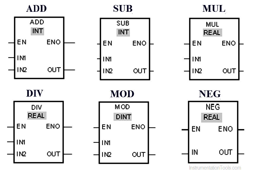
Siemens PLC Mathematics Instructions : Implement ADD, SUB, MUL, DIV, MOD and NEG instructions in S7-1200 PLC using ladder diagram language.

Last updated: November 3, 2023 3:14 pm
Editorial Staff
PLC Tutorials
No Comments
Share
4 Min Read
SHARE

This is Program for Siemens PLC Mathematics Instructions.

Contents
Siemens PLC Math InstructionsProblem DiagramSolutionList of Inputs/OutputsPLC Ladder diagram for mathematical instructionsProgram Description

Siemens PLC Math Instructions

Implement ADD, SUB, MUL, DIV, MOD and NEG instructions in S7-1200 PLC using ladder diagram language.

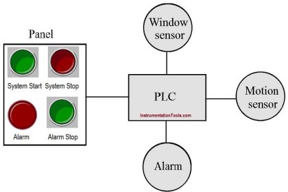
Problem Diagram
Siemens PLC Math Instructions

Solution

We can use the Add instruction to add the value at input IN1 and the value at input IN2 and query the sum at output OUT (OUT := IN1+IN2).

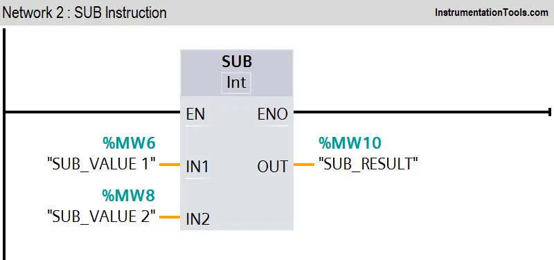
Subtract instruction is used to subtract the value at input IN2 from the value at input IN1 and query the difference at output OUT (OUT := IN1-IN2).

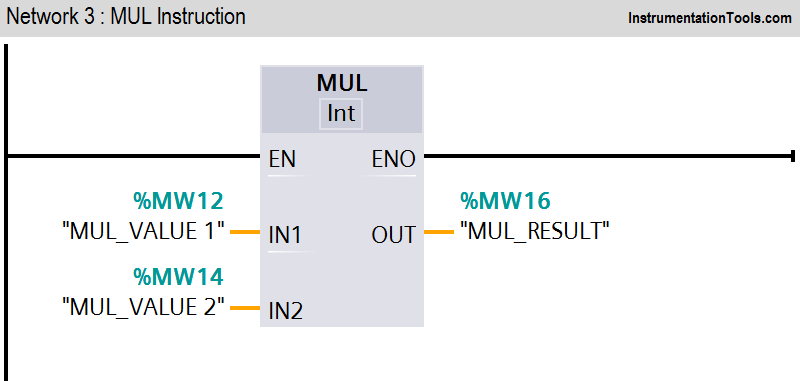
Multiply instruction is used to multiply the value at input IN1 with the value at input IN2 and query the product at output OUT (OUT := IN1*IN2).

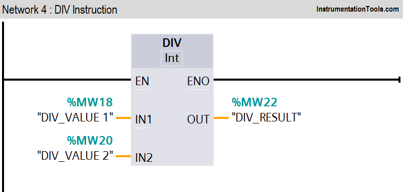
Divide instruction is used to divide the value at input IN1 by the value at input IN2 and query the quotient at output OUT (OUT := IN1/IN2).

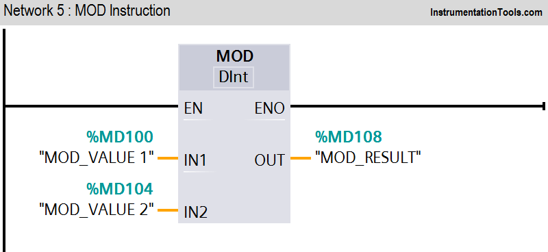
We can use the Return remainder of division instruction to divide the value at input IN1 by the value at input IN2 and query the remainder of division at output OUT.

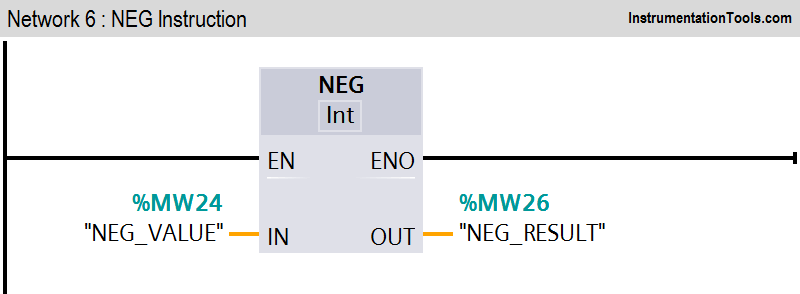
We can use the “Create twos complement” instruction to change the sign of the value at the IN input and query the result at the OUT output. If there is a positive value at input IN, for example, the negative equivalent of this value is sent to output OUT.

List of Inputs/Outputs

M memory

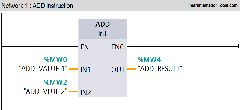
  • MW0 :- “ADD_VALUE 1”
  • MW2 :- “ADD_VALUE 2”
  • MW4 :- “ADD_RESULT”
  • MW6 :- “SUB_VALUE 1”
  • MW8 :- “SUB_VALUE 2”
  • MW10 :- “SUB_RESULT”
  • MW12 :- “MUL_VALUE 1”
  • MW14 :- “MUL_VALUE 2”
  • MW16 :- “MUL_RESULT”
  • MW18 :- “DIV_VALUE 1”
  • MW20 :- “DIV_VALUE 2”
  • MW22 :- “DIV_RESULT”
  • MW24 :- “NEG_VALUE”
  • MW226 :- “NEG_RESULT”
  • MD100 :- “MOD_VALUE 1”
  • MD104 :- “MOD_VALUE 2”
  • MD108 :- “MOD_RESULT”

PLC Ladder diagram for mathematical instructions
PLC ADD Instruction
PLC SUB Instruction

PLC MUL Instruction PLC DIV Instruction PLC MOD Instruction PLC NEG Instruction Program Description

In this program we have used Siemens S7-1200 PLC and TIA Portal Software for programming.

Network 1:

The value of MW0 is added to the value of MW2.The result of the addition is stored in the MW4.

Network2:

The value of MW6 is subtracted from the value of MW8.The result of the subtraction is stored in MW10.

Network 3:

The value of operand MW12 is multiplied by the value of MW14. The result of the multiplication is stored in MW16.

Network 4:

The value of operand MW18 is divided by the value of MW20. The division result is stored in MW22.

Network 5:

The value of MD100 is divided by the value of MD104. The remainder of division is stored in operand MD108.

Network 6:

The sign of the value at input MW24 is changed and the result is provided at output MW26.

Author: Bhavesh

If you liked this article, then please subscribe to our YouTube Channel for PLC and SCADA video tutorials.

You can also follow us on Facebook and Twitter to receive daily updates.

Read Next:

  • Conveyor System using PLC
  • PLC Program using Counters
  • Documents in a PLC System
  • Allen Bradley PLC Subroutines
  • PLC Analog and Network I/O
Don't Miss Our Updates
Be the first to get exclusive content straight to your email.
We promise not to spam you. You can unsubscribe at any time.
Invalid email address
You've successfully subscribed !

Continue Reading

PLC Input Output Modules
Animation of Electromagnetic Relay
What is Complementary Split Range Control (CSRC)?
Yokogawa DCS and SIS System Architecture
Basic Concepts of the Safety Relay
AI, AO, DI, DO Questions (PLC I/O Types)
Share This Article
Facebook Whatsapp Whatsapp LinkedIn Copy Link
Share
Leave a Comment

Leave a Reply Cancel reply

Your email address will not be published. Required fields are marked *

Stay Connected

128.3kFollowersLike
69.1kFollowersFollow
208kSubscribersSubscribe
38kFollowersFollow

Categories

Explore More

How to use Converters in PLC
PLC Connection between Instrument, Junction Box, Marshalling & System Cabinet
Difference Between SCADA and HMI
Intrinsically Safe Barriers Questions and Answers
Real-Time Clock in Omron PLC? – CX Programmer
SCADA and HMI Systems – Differences, Similarities, Purpose
Flip-Flop PLC Programming: Lights with Adjustable Timers
Unknown Do’s Need to Know as a PLC Programmer

Keep Learning

PLC engineering software

How to Download GX Works? Mitsubishi PLC Software

PLC Program for Boolean Expression

PLC Program for Boolean Expression

Interlock Philosophy

Types of Interlocks

Function Block Program Simulation

What are Functions in PLC Programming? (FCs)

Studio 5000 Define Program or Operator Control in Functional Block Diagram

Studio 5000: Define Program or Operator Control in Functional Block Diagram

Compare DCS, PLC, RTU

Difference between DCS, PLC, and RTU ?

Exhaust Fan Control

Exhaust Fan Control: Example of PLC Timer Programming

PLC FBD Example for Tank Liquid Heating Control by Steam Flow

PLC FBD Example for Tank Liquid Heating Control by Steam Flow

Learn More

Lead Acid Battery Operation

How does a Lead Acid Battery Work?

Top 100 MATLAB Projects for Engineering Students

Top 100 MATLAB Projects for Engineering Students

Typical Purging Installation

Purging of Instruments

Advantages and Disadvantages of Network Topology

Advantages & Disadvantages of Different Vibration Sensors

Timer STL Programming

Timers using Statement List (STL) PLC Programming

Industrial Automation Solution

How to Choose the Right Industrial Automation Solution?

How to Locate Faults in Cables? - Fault Analysis and Location

How to Locate Faults in Cables? – Fault Analysis & Location

Measuring Instruments Questions and Answers

150+ Measuring Instruments Questions and Answers

Follow US
All rights reserved. Reproduction in whole or in part without written permission is prohibited.
Welcome Back!

Sign in to your account

Username or Email Address
Password

Lost your password?