Inst ToolsInst ToolsInst Tools
  • Courses
  • Automation
    • PLC
    • Control System
    • Safety System
    • Communication
    • Fire & Gas System
  • Instrumentation
    • Design
    • Pressure
    • Temperature
    • Flow
    • Level
    • Vibration
    • Analyzer
    • Control Valve
    • Switch
    • Calibration
    • Erection & Commissioning
  • Interview
    • Instrumentation
    • Electrical
    • Electronics
    • Practical
  • Q&A
    • Instrumentation
    • Control System
    • Electrical
    • Electronics
    • Analog Electronics
    • Digital Electronics
    • Power Electronics
    • Microprocessor
  • Request
Search
  • Books
  • Software
  • Projects
  • Process
  • Tools
  • Basics
  • Formula
  • Power Plant
  • Root Cause Analysis
  • Electrical Basics
  • Animation
  • Standards
  • 4-20 mA Course
  • Siemens PLC Course
Reading: PLC Program for Food Processing Industry
Share
Font ResizerAa
Inst ToolsInst Tools
Font ResizerAa
  • Courses
  • Design
  • PLC
  • Interview
  • Control System
Search
  • Courses
  • Automation
    • PLC
    • Control System
    • Safety System
    • Communication
    • Fire & Gas System
  • Instrumentation
    • Design
    • Pressure
    • Temperature
    • Flow
    • Level
    • Vibration
    • Analyzer
    • Control Valve
    • Switch
    • Calibration
    • Erection & Commissioning
  • Interview
    • Instrumentation
    • Electrical
    • Electronics
    • Practical
  • Q&A
    • Instrumentation
    • Control System
    • Electrical
    • Electronics
    • Analog Electronics
    • Digital Electronics
    • Power Electronics
    • Microprocessor
  • Request
Follow US
All rights reserved. Reproduction in whole or in part without written permission is prohibited.
Inst Tools > Blog > PLC Tutorials > PLC Program for Food Processing Industry

PLC Program for Food Processing Industry

This is a PLC Program to detect burned chips and remove them by using PLC. Learn PLC programming with food industry examples.

Last updated: November 3, 2023 12:37 pm
Editorial Staff
PLC Tutorials
1 Comment
Share
5 Min Read
SHARE

This is a PLC Program to detect burned chips and remove them by using PLC. Learn PLC programming with food industry examples.

Contents
Food Processing IndustryProblem DiagramPLC SolutionList of inputs and outputsPLC Program for detecting burned chips and removing themPLC Program ExplanationResult

Food Processing Industry

Problem Description

Potato chips are made in the company and sent to final packing. As per the process we need to identify the chips because in chips some chips might be burned.

Burned chips should be removed from the conveyor. Make a PLC program for the application which can detect burned chips and remove them.

Problem Diagram

PLC Program for Food Processing

PLC Solution

To detect burned chips light sensor are used. Light dependent resistors (LDR) are used to detect the burned chips.

Blowers are used to throw away the burned chips from the conveyor whenever burned chips detected.

Blowers are used to throw away burned chips from the conveyor. Here we used two blowers, number of blowers depend on the size of the conveyor.

Time measurement is necessary for blower cycle. Here we measure time taken by chips to reach from light source to blower.

Note:- Here we consider simple application for detecting burned chips on the conveyor and remove them. We have taken here light source to detect burned chips on the bases of darkness of the chips.

List of inputs and outputs

Digital Inputs

  • START PB :- I0.0
  • STOP PB :- I0.1
  • LDR 1:- I0.2
  • LDR 2 :- I0.3

Digital Outputs

  • Cycle ON :- Q0.0
  • Conveyor :- Q0.1
  • Light source :- Q0.2
  • Blower 1 :- Q0.3
  • Blower 2 :- Q0.4

M memory

  • Relay coil 1 : M0.0
  • Relay coil 2: M0.1

PLC Program for detecting burned chips and removing them

PLC Ladder Logic for Food Processing
PLC Program Food Processing
burned chips on the conveyor
detect burned chips
Food Industry PLC Ladder
PLC Logic Food
PLC Logic Food Plant

PLC Program Explanation

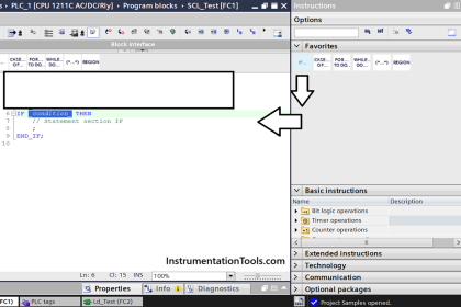
For this application, we use S7-300 PLC and TIA portal software for programming. We can implement this logic by using other PLC also.
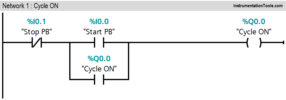
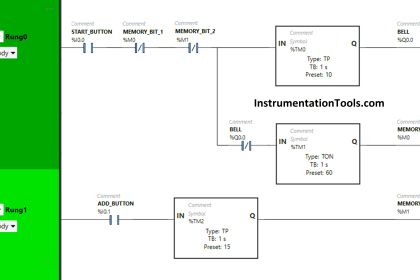
Network 1:

In first network we used latching circuit for cycle ON. Here we used START PB (I0.0 ) to start the cycle and STOP PB (I0.1) to stop the cycle.
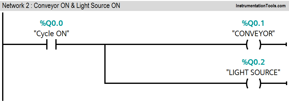
Network 2:

When cycle is ON (Q0.0), Conveyor (Q0.1) and light source (Q0.2) will be ON.
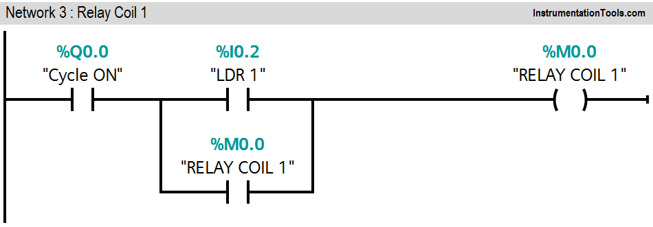
Network 3:

Cycle is ON and LDR 1 (I0.2) is detected, Relay coil 1(M0.0) will be ON
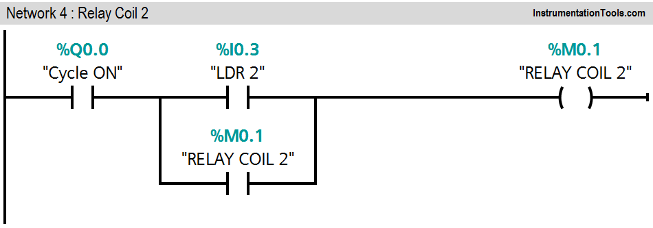
Network 4:

Cycle is ON and LDR 2 (I0.3) is detected, Relay coil 2 (M0.1) will be ON
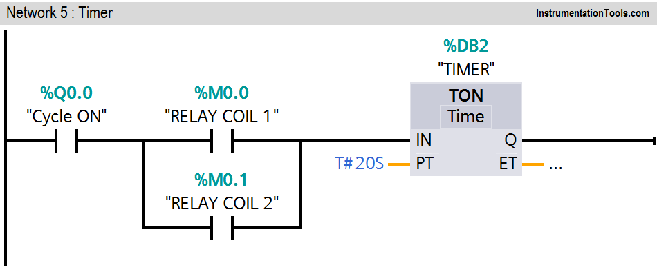
Network 5:

Either relay coil 1 (M0.0) or relay coil 2 (M0.1) is ON, Timer instruction will be executed. During this operation cycle is ON.
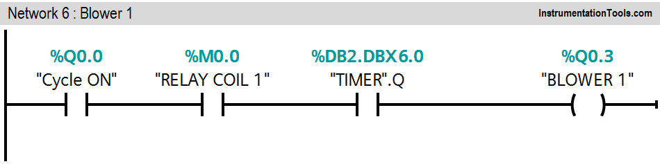
Network 6:

When cycle is ON (Q0.0) and timer output is ON, blower 1 will be ON.
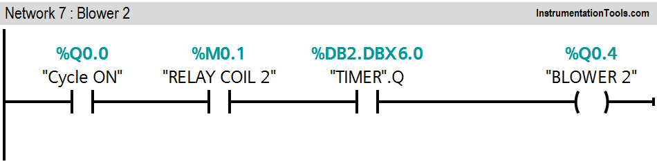
Network 7:

When cycle is ON (Q0.0) and timer output is ON, blower 2 will be ON.

When LDR sensors detect burned chips on the conveyor, blower’s timer (20s) will be ON and it will throw away the burned chips from the conveyor. Here we assumed 20s travelling time taken by chips to reach from light source to blowers.

Number of blowers is depended on the size of the conveyor.

Note:- Above application may be different from actual application. This example is only for explanation purpose only. We can implement this logic in other PLC also. This is the simple concept of detecting burned chips on the conveyor and remove them by PLC logic. All parameters considered in example are for explanation purpose only, parameters may be different in actual applications.

Result

PLC Logic Food Processing Industry

Author: Bhavesh

If you liked this article, then please subscribe to our YouTube Channel for PLC and SCADA video tutorials.

You can also follow us on Facebook and Twitter to receive daily updates.

Read Next:

  • PLC Reads from Field Transmitters
  • Troubleshoot a PLC System
  • PLC Architecture
  • Difference between PLC & DCS
  • Automation Engineers Questions
Don't Miss Our Updates
Be the first to get exclusive content straight to your email.
We promise not to spam you. You can unsubscribe at any time.
Invalid email address
You've successfully subscribed !

Continue Reading

PLC Example on Switch Program with Timers
Troubleshooting PLC Permissive Inputs
PLC to PLC Communication using S7 Connection PUT & GET Instructions
What are FIFO and LIFO Sequences in PLC?
Problem on PLC, HMI, VFD, and Motor Circuit
Various Communication Protocols in PLC
Share This Article
Facebook Whatsapp Whatsapp LinkedIn Copy Link
Share
1 Comment
  • Apurva Khartad says:
    February 19, 2021 at 4:02 pm

    Much needed explaination Sir. Thank you so much

    Reply

Leave a Reply Cancel reply

Your email address will not be published. Required fields are marked *

Stay Connected

128.3kFollowersLike
69.1kFollowersFollow
210kSubscribersSubscribe
38kFollowersFollow

Categories

Explore More

PLC Programming for Weight-Based Packaging
How to Convert Voltage to Current using Resistor ?
Siemens PLC Tia Portal – OB100 Start-up Organization Block
Batch Simulator PLC Example Program using LogixPro Simulator
Drilling Process using PLC Program
PLC Program for Latching and unlatching Circuit
PLC Timer Instructions
Example PLC Program to Control a Pump based on Level Sensors

Keep Learning

memory types in siemens plc

Memory Structure of Siemens PLC

Industrial motor control using PLC instruction list programming

PLC Instruction List for Motor Reverse and Forward Direction

Free Allen Bradley PLC Training Course

Free Allen Bradley PLC Ladder Logic Training Course

PLC Program to Control Level of Two Tanks

PLC Level Control of Two Tanks

PLC Program for Analog Input Sampling

PLC Analog Input Sampling Ladder Logic

PLC Programming Example on LED Control

PLC Programming Example on LED Control

ON DELAY TIMER AS OFF DELAY TIMER

How to Interchange ON Delay Timer and OFF Delay Timer in a PLC

PLC Program using Logic GATEs

PLC Logic GATE Program

Learn More

Factors Affecting Inductance

Factors Affecting Inductance

Brass Cable Gland

How to Choose a Brass Cable Gland Manufacturer?

Digital Electronics Multiple Choice Questions

Counter IC Objective Questions

Simplified Induction Motor - Cross Section

Siemens Standard Drives Application Handbook (PDF)

Communication between Factory IO and Siemens Tia Portal

Communication between Factory IO and Siemens Tia Portal

Four Wire RTD Circuit

What is a Four-wire RTD ?

Ultrasonic Tank Gauging

Ultrasonic Tank Gauging

Displacer Level Sensor Working Animation

Displacer Level Sensor Working Animation

Menu

  • About
  • Privacy Policy
  • Copyright

Quick Links

  • Learn PLC
  • Helping Hand
  • Part Time Job

YouTube Subscribe

Follow US
All rights reserved. Reproduction in whole or in part without written permission is prohibited.
Welcome Back!

Sign in to your account

Username or Email Address
Password

Lost your password?