Inst ToolsInst ToolsInst Tools
  • Ask
  • Courses
  • Videos
  • Q & A
    • Interview
      • Instrumentation
      • Electronics
      • Electrical
      • Practical Questions
    • MCQ
      • Instrumentation MCQ
      • Electrical MCQ
      • Electronics MCQ
      • Control Systems MCQ
      • Analog Electronics MCQ
      • Digital Electronics MCQ
      • Power Electronics MCQ
      • Microprocessor MCQ
      • Multiple Choice Questions
  • EE
    • Electronics
      • Electronics Q & A
      • Electronic Basics
      • Electronic Devices & Circuits
      • Electronics Animation
      • Digital Electronics
    • Electrical
      • Electrical Basics
      • Electrical Q & A
      • Power Electronics
      • Electrical Machines
      • Electrical Animation
      • Power Systems
      • Switchgear & Protection
      • Transmission & Distribution
  • Measure
    • Control Valves
    • Calibration
    • Temperature
    • Pressure
    • Flow
    • Level
    • Analyzers
    • Switches
    • Vibration
    • Solenoid Valve
  • Control
    • PLC Tutorials
    • Control Systems
    • Safety Instrumented System (SIS)
    • Communication
    • Fire & Gas System
  • More
    • Design
    • Tools
    • Animation
    • Basics
    • Formulas
    • Standards
    • TextBooks
    • Common
    • Software
    • Excel Tools
    • Erection & Commissioning
    • Process Fundamentals
    • Videos
    • Books
Search
All rights reserved. Reproduction in whole or in part without written permission is prohibited.
Reading: Three Phase Transformer Connections
Share
Notification Show More
Font ResizerAa
Inst ToolsInst Tools
Font ResizerAa
  • Courses
  • PLC Tutorials
  • Control Systems
Search
  • Ask
  • Courses
  • Videos
  • Q & A
    • Interview
    • MCQ
  • EE
    • Electronics
    • Electrical
  • Measure
    • Control Valves
    • Calibration
    • Temperature
    • Pressure
    • Flow
    • Level
    • Analyzers
    • Switches
    • Vibration
    • Solenoid Valve
  • Control
    • PLC Tutorials
    • Control Systems
    • Safety Instrumented System (SIS)
    • Communication
    • Fire & Gas System
  • More
    • Design
    • Tools
    • Animation
    • Basics
    • Formulas
    • Standards
    • TextBooks
    • Common
    • Software
    • Excel Tools
    • Erection & Commissioning
    • Process Fundamentals
    • Videos
    • Books
Follow US
All rights reserved. Reproduction in whole or in part without written permission is prohibited.
Inst Tools > Blog > Electrical Theory > Three Phase Transformer Connections

Three Phase Transformer Connections

Last updated: August 7, 2018 10:37 am
Editorial Staff
Electrical Theory
No Comments
Share
4 Min Read
SHARE

So far, our discussion has dealt with the operation of single-phase transformers. Three-phase transformer operation is identical except that three single-phase windings are used. These windings may be connected in wye, delta, or any combination of the two.

Contents
Delta ConnectionWye ConnectionCombinations of Delta and Wye Transformer Connections

Delta Connection

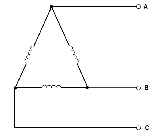
In the delta connection, all three phases are connected in series to form a closed loop (Figure 1).

delta connected generator

Figure 1 : Delta Connection

Wye Connection

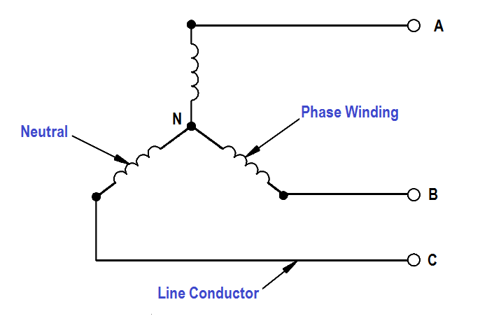
In the wye connection, three common ends of each phase are connected together at a common terminal (marked “N” for neutral), and the other three ends are connected to a three-phase line (Figure 2).

Wye connected generator

Figure 2 :  Wye Connection

Combinations of Delta and Wye Transformer Connections

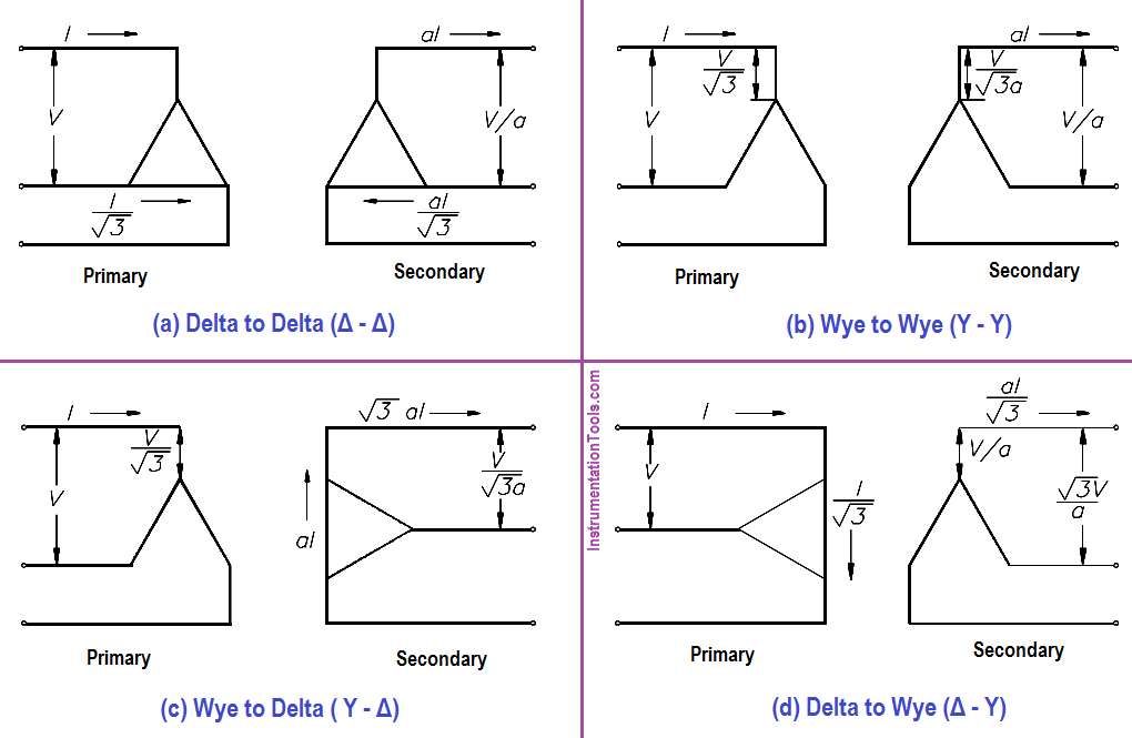
A three-phase transformer may have three separate but identical single-phase (1φ) transformers or a single 3φ unit containing three-phase windings. The transformer windings may be connected to form a 3φ bank in any of four different ways (Figure 3).

Three Phase Transformer Connections

Figure 3 :  3φ Transformer Connections

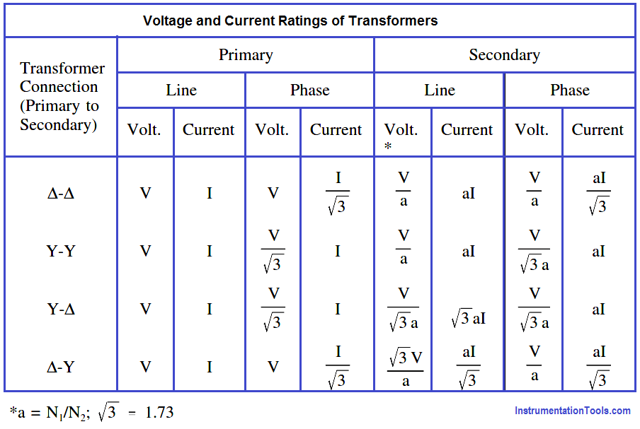
Figure 3 shows the voltages and currents in terms of applied line voltage (V) and line current (I), where the turns ratio (a) is equal to one. Voltage and current ratings of the individual transformers depend on the connections (Figure 3) and are indicated by below Table for convenience of calculations.

Voltage and Current Ratings of Transformers

Example 1:

If line voltage is 440 V to a 3φ transformer bank, find the voltage across each primary winding for all four types of transformer connections.

Solution :

Δ – Δ : Primary Voltage = V = 440 Volts

Y – Y : Primary Voltage = V/√3 = 440/1.73 = 254.3 volts

Y – Δ : Primary Voltage = V/√3 = 440/1.73 = 254.3 volts

Δ – Y : Primary Voltage = V = 440 Volts

Example 2:

If line current is 10.4 A in a 3φ transformer connection, find the primary phase current.

Solution :

Δ – Δ : Primary Phase Current = I/√3 = 10.4/1.73 = 6 amps

Y – Y : Primary Phase Current = I = 10.4 amps

Y – Δ : Primary Phase Current = I = 10.4 amps

Δ – Y : Primary Phase Current = I/√3 = 10.4/1.73 = 6 amps

Example 3:

Find the secondary line current and phase current for each type of transformer connection, if primary line current is 20 amps, and the turns ratio is 4:1.

Solution :

∆-∆ : Secondary line current = 4(20) = 80 amps

∆-∆ : Secondary Phase current = aI/√3 = (4×20) / 1.73 = 46.2 amps

Y-Y : Second line current = aI = 4(20) = 80 amps

Y-Y : Second phase current = aI = 4(20) = 80 amps

Y-∆ : Second line current = √3aI = 4(20)(1.73) = 138.4 amps

Y-∆ : Second phase current = aI = 4(20) = 80 amps

∆-Y : Second line current = aI/√3 = (4×20) / 1.73 = 46.2 amps

∆-Y : Second phase current = aI/√3 = (4×20) / 1.73 = 46.2 amps
Don't Miss Our Updates
Be the first to get exclusive content straight to your email.
We promise not to spam you. You can unsubscribe at any time.
Invalid email address
You've successfully subscribed !
Calculate Power in Parallel RC Circuit
Single Phase Power Wiring Schemes
4-Wire, Three-Phase Delta Wiring System
DC Motor Theory
Calculate Power in Series RL Circuit
Share This Article
Facebook Whatsapp Whatsapp LinkedIn Copy Link
Share
Leave a Comment

Leave a Reply Cancel reply

Your email address will not be published. Required fields are marked *

Stay Connected

128.3kFollowersLike
69.1kFollowersFollow
208kSubscribersSubscribe
38kFollowersFollow

Categories

Recent Comments

  • Kamli on Top Free PLC Software
  • Guifty Shimica on Top Non-PLC Certification Courses for Automation Professionals
  • Guifty Shimica on Top Non-PLC Certification Courses for Automation Professionals
  • MIHARITSOA Aina Sitraka on Top Non-PLC Certification Courses for Automation Professionals

Related Articles

Battery Hazard

Battery Hazards

Current in a Capacitor

Capacitance and Capacitive Reactance

DC Motor Action

DC Motor Speed

Inductors in parallel

Series and Parallel Inductors

Left-hand Rule for Current Carrying Conductors

Magnetism

Parallel Circuit Unknown Resistance

Simplified Formulas for Parallel Circuit Resistance Calculations

relationship between resistance, reactance, and impedance

Impedance

DC Circuit Node Equations

DC Circuit Analysis Node Equations

More Articles

Power Systems Questions & Answers

Power Systems MCQ Series 10

Pressure Transmitters Filled impulse lines

Pressure Transmitters Filled impulse lines

different PLC brands of Distributed IO

What is Distributed IO? – Decentralized Peripherals in PLC

Advantages & Disadvantages of CNC Milling

What are the Advantages & Disadvantages of CNC Milling?

Coriolis Mass Flow Meter Working Animation

Coriolis Meter Explained with Animation

Control Valve with Positioner

 Control Valve Accessories – Principle, Purpose, Advantages

Electronic Devices & Circuits Objective Questions

Electronic Devices & Circuits Quiz – Set 10

Power Electronics Objective Questions

Power Electronics Diode Circuits Questions and Answers

Follow US
All rights reserved. Reproduction in whole or in part without written permission is prohibited.
Welcome Back!

Sign in to your account

Username or Email Address
Password

Lost your password?