Inst ToolsInst ToolsInst Tools
  • Courses
  • Automation
    • PLC
    • Control System
    • Safety System
    • Communication
    • Fire & Gas System
  • Instrumentation
    • Design
    • Pressure
    • Temperature
    • Flow
    • Level
    • Vibration
    • Analyzer
    • Control Valve
    • Switch
    • Calibration
    • Erection & Commissioning
  • Interview
    • Instrumentation
    • Electrical
    • Electronics
    • Practical
  • Q&A
    • Instrumentation
    • Control System
    • Electrical
    • Electronics
    • Analog Electronics
    • Digital Electronics
    • Power Electronics
    • Microprocessor
  • Request
Search
  • Books
  • Software
  • Projects
  • Process
  • Tools
  • Basics
  • Formula
  • Power Plant
  • Root Cause Analysis
  • Electrical Basics
  • Animation
  • Standards
  • 4-20 mA Course
  • Siemens PLC Course
Reading: Series-Wound Motor
Share
Font ResizerAa
Inst ToolsInst Tools
Font ResizerAa
  • Courses
  • Design
  • PLC
  • Interview
  • Control System
Search
  • Courses
  • Automation
    • PLC
    • Control System
    • Safety System
    • Communication
    • Fire & Gas System
  • Instrumentation
    • Design
    • Pressure
    • Temperature
    • Flow
    • Level
    • Vibration
    • Analyzer
    • Control Valve
    • Switch
    • Calibration
    • Erection & Commissioning
  • Interview
    • Instrumentation
    • Electrical
    • Electronics
    • Practical
  • Q&A
    • Instrumentation
    • Control System
    • Electrical
    • Electronics
    • Analog Electronics
    • Digital Electronics
    • Power Electronics
    • Microprocessor
  • Request
Follow US
All rights reserved. Reproduction in whole or in part without written permission is prohibited.
Inst Tools > Blog > Electrical Theory > Series-Wound Motor

Series-Wound Motor

Last updated: July 29, 2018 12:25 pm
Editorial Staff
Electrical Theory
No Comments
Share
1 Min Read
SHARE

Since the armature and field in a series-wound motor are connected in series, the armature and field currents become identical, and the torque can be expressed as shown in below Equation.

T = K Ia2

The torque-vs-speed characteristics of a series-wound motor with a constant voltage source are shown in Figure 9. As the speed decreases, the torque for a series – wound motor increases sharply. As load is removed from a series motor, the speed will increase sharply. For these reasons, series-wound motors must have a load connected to prevent damage from high speed conditions.

Series - Wound DC Motor

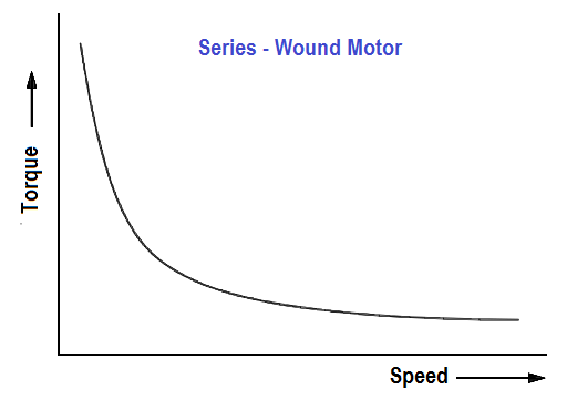
Figure 9 : Torque-vs-Speed for a Series-Wound Motor

Series-Wound Motor Applications

The advantage of a series-wound motor is that it develops a large torque and can be operated at low speed. It is a motor that is well-suited for starting heavy loads; it is often used for industrial cranes and winches where very heavy loads must be moved slowly and lighter loads moved more rapidly.

Don't Miss Our Updates
Be the first to get exclusive content straight to your email.
We promise not to spam you. You can unsubscribe at any time.
Invalid email address
You've successfully subscribed !

Continue Reading

AC Generation
Applying Kirchhoff’s Current Law
Single Phase Power Wiring Schemes
Single Line Diagram
High Voltage Circuit Breaker Principle
Parallel Short Circuit Faults
Share This Article
Facebook Whatsapp Whatsapp LinkedIn Copy Link
Share
Leave a Comment

Leave a Reply Cancel reply

Your email address will not be published. Required fields are marked *

Stay Connected

128.3kFollowersLike
69.1kFollowersFollow
210kSubscribersSubscribe
38kFollowersFollow

Categories

Explore More

Circuit Breaker Control Circuit
Multimeter & Megger Principle
Transformer Voltage Ratio
Capacitor
DC Motor Speed
Moving Iron Vane Meter Movement
Impedance in RC Circuits
Impedance in RL Circuits

Keep Learning

Capacitor and Symbols

Capacitance

Three-Phase Wye Wiring System

4-Wire, Three-Phase Wye Wiring System

Unbalanced 3 Phase Loads

Unbalanced 3 Phase Loads

Transformer Efficiency

Transformer Efficiency

Schematic Diagram

Schematic Diagram

Electrical Symbols

Electrical Symbols

Half-Wave Rectifier Circuit

Half-Wave Rectifier Circuit

Series Parallel Circuit Analysis

Series – Parallel Circuit Analysis

Learn More

What is Chromatography

What is Chromatography ?

CRA Module in Schneider PLC

CRA Module in Schneider PLC – Remote IO Adapter Module

Top 80+ Valve Questions and Answers

Top 80+ Valve Questions and Answers

Battery Hazard

Battery Hazards

Allen Bradley SLC 500 PLC Programming

Electric Circuits Objective Questions

Electric Circuits Objective Questions – Set 18

Air Lock Relay Working Principle

Control Valve Air Lock Relay Working Principle

Motor Operated Valve Functional Testing

Motor Operated Valve Functional Testing

Menu

  • About
  • Privacy Policy
  • Copyright

Quick Links

  • Learn PLC
  • Helping Hand
  • Part Time Job

YouTube Subscribe

Follow US
All rights reserved. Reproduction in whole or in part without written permission is prohibited.
Welcome Back!

Sign in to your account

Username or Email Address
Password

Lost your password?