Inst ToolsInst ToolsInst Tools
  • Ask
  • Courses
  • Videos
  • Q & A
    • Interview
      • Instrumentation
      • Electronics
      • Electrical
      • Practical Questions
    • MCQ
      • Instrumentation MCQ
      • Electrical MCQ
      • Electronics MCQ
      • Control Systems MCQ
      • Analog Electronics MCQ
      • Digital Electronics MCQ
      • Power Electronics MCQ
      • Microprocessor MCQ
      • Multiple Choice Questions
  • EE
    • Electronics
      • Electronics Q & A
      • Electronic Basics
      • Electronic Devices & Circuits
      • Electronics Animation
      • Digital Electronics
    • Electrical
      • Electrical Basics
      • Electrical Q & A
      • Power Electronics
      • Electrical Machines
      • Electrical Animation
      • Power Systems
      • Switchgear & Protection
      • Transmission & Distribution
  • Measure
    • Control Valves
    • Calibration
    • Temperature
    • Pressure
    • Flow
    • Level
    • Analyzers
    • Switches
    • Vibration
    • Solenoid Valve
  • Control
    • PLC Tutorials
    • Control Systems
    • Safety Instrumented System (SIS)
    • Communication
    • Fire & Gas System
  • More
    • Design
    • Tools
    • Animation
    • Basics
    • Formulas
    • Standards
    • TextBooks
    • Common
    • Software
    • Excel Tools
    • Erection & Commissioning
    • Process Fundamentals
    • Videos
    • Books
Search
All rights reserved. Reproduction in whole or in part without written permission is prohibited.
Reading: Capacitive Time Constant
Share
Notification Show More
Font ResizerAa
Inst ToolsInst Tools
Font ResizerAa
  • Courses
  • PLC Tutorials
  • Control Systems
Search
  • Ask
  • Courses
  • Videos
  • Q & A
    • Interview
    • MCQ
  • EE
    • Electronics
    • Electrical
  • Measure
    • Control Valves
    • Calibration
    • Temperature
    • Pressure
    • Flow
    • Level
    • Analyzers
    • Switches
    • Vibration
    • Solenoid Valve
  • Control
    • PLC Tutorials
    • Control Systems
    • Safety Instrumented System (SIS)
    • Communication
    • Fire & Gas System
  • More
    • Design
    • Tools
    • Animation
    • Basics
    • Formulas
    • Standards
    • TextBooks
    • Common
    • Software
    • Excel Tools
    • Erection & Commissioning
    • Process Fundamentals
    • Videos
    • Books
Follow US
All rights reserved. Reproduction in whole or in part without written permission is prohibited.
Inst Tools > Blog > Electrical Theory > Capacitive Time Constant

Capacitive Time Constant

Last updated: July 27, 2018 11:02 am
Editorial Staff
Electrical Theory
No Comments
Share
2 Min Read
SHARE

When a capacitor is connected to a DC voltage source, it charges very rapidly. If no resistance was present in the charging circuit, the capacitor would become charged almost instantaneously. Resistance in a circuit will cause a delay in the time for charging a capacitor. The exact time required to charge a capacitor depends on the resistance (R) and the capacitance (C) in the charging circuit.

The below Equation illustrates this relationship.

TC = R C

where

TC = capacitive time constant (sec)
R = resistance (ohms)
C = capacitance (farad)

The capacitive time constant is the time required for the capacitor to charge to 63.2 percent of its fully charged voltage. In the following time constants, the capacitor will charge an additional 63.2 percent of the remaining voltage. The capacitor is considered fully charged after a period of five time constants (Figure 18).

Capacitive Time Constant for Charging Capacitor

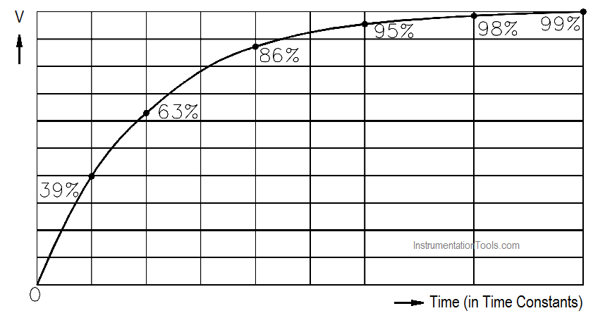
Figure 18 Capacitive Time Constant for Charging Capacitor

The capacitive time constant also shows that it requires five time constants for the voltage across a discharging capacitor to drop to its minimum value (Figure 19).

Capacitive Time Constant for Discharging Capacitor

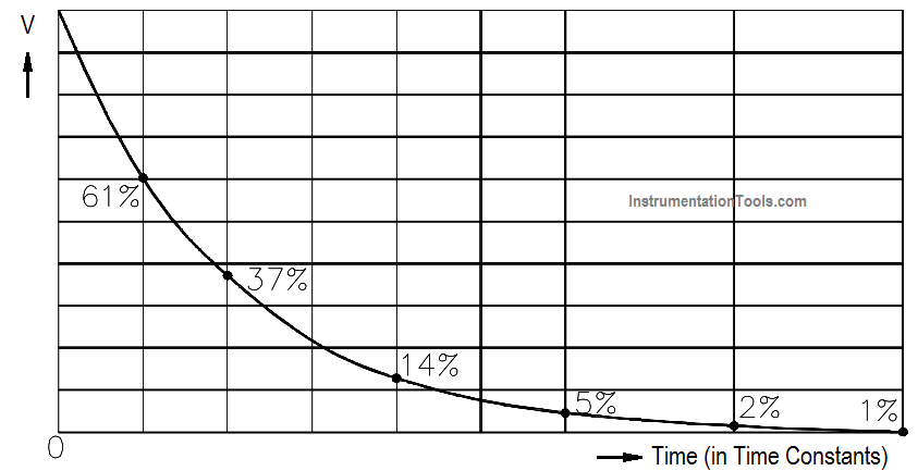
Figure 19 Capacitive Time Constant for Discharging Capacitor

Example:

Find the time constant of a 100 µF capacitor in series with a 100Ω resistor (Figure 20).

Example - Capacitive Time Constant

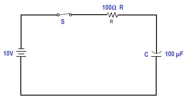
Figure 20 Example – Capacitive Time Constant

TC = R C

TC = 100 µF x 100Ω

TC = 0.01 seconds

Don't Miss Our Updates
Be the first to get exclusive content straight to your email.
We promise not to spam you. You can unsubscribe at any time.
Invalid email address
You've successfully subscribed !
Circuit Breaker Control Circuit
Electric Circuit : Open & Short Circuits
AC Generation Analysis : Effective Values, Phase Angle and Frequency
Three Phase Transformer Connections
Voltmeters
Share This Article
Facebook Whatsapp Whatsapp LinkedIn Copy Link
Share
Leave a Comment

Leave a Reply Cancel reply

Your email address will not be published. Required fields are marked *

Stay Connected

128.3kFollowersLike
69.1kFollowersFollow
208kSubscribersSubscribe
38kFollowersFollow

Categories

Recent Comments

  • Guifty Shimica on Top Non-PLC Certification Courses for Automation Professionals
  • Guifty Shimica on Top Non-PLC Certification Courses for Automation Professionals
  • MIHARITSOA Aina Sitraka on Top Non-PLC Certification Courses for Automation Professionals
  • Vaishnavi on Free Instrumentation Course for Trainee Engineers

Related Articles

Half-Wave Rectifier Circuit

Half-Wave Rectifier Circuit

Series Circuit

Series Circuit

Auto Transformer Schematic

Classification of Transformers

Voltage and Current Phase Relationships in an Inductive Circuit

Voltage and Current Phase Relationships in an Inductive Circuit

Battery Hazard

Battery Hazards

Moving Iron Vane Meter Movement

Moving Iron Vane Meter Movement

Battery Interview QuBattery Interview Question and Answersestion and Answers

Battery Terminology

Parallel RLC Circuit

Impedance in RLC Circuits

More Articles

wedge Flow meter

What is a Segmental Wedge Flow Meter?

What is a Database Server

What is a Database Server? – Types, Comparison

PID Controller Loop Tuning Questions and Answers

PID Controller Loop Tuning Questions and Answers – Part 2

Top 10 Common Mistakes on Electrical Systems

Top 10 Common Mistakes on Electrical Systems

Insertion flow meters

What is an Insertion Flow Meter? – Types, Principle, Advantages

Rotor Angle Stability of Synchronous Generators in Power System

Rotor Angle Stability of Synchronous Generators in Power System

Chromatography Questions & Answers

Detection System of Liquid Chromatography Questions & Answers

Mass Spectrometer Questions and Answers

Magnetic Deflection Mass Spectrometer Questions & Answers

Follow US
All rights reserved. Reproduction in whole or in part without written permission is prohibited.
Welcome Back!

Sign in to your account

Username or Email Address
Password

Lost your password?