Inst ToolsInst ToolsInst Tools
  • Ask
  • Courses
  • Videos
  • Q & A
    • Interview
      • Instrumentation
      • Electronics
      • Electrical
      • Practical Questions
    • MCQ
      • Instrumentation MCQ
      • Electrical MCQ
      • Electronics MCQ
      • Control Systems MCQ
      • Analog Electronics MCQ
      • Digital Electronics MCQ
      • Power Electronics MCQ
      • Microprocessor MCQ
      • Multiple Choice Questions
  • EE
    • Electronics
      • Electronics Q & A
      • Electronic Basics
      • Electronic Devices & Circuits
      • Electronics Animation
      • Digital Electronics
    • Electrical
      • Electrical Basics
      • Electrical Q & A
      • Power Electronics
      • Electrical Machines
      • Electrical Animation
      • Power Systems
      • Switchgear & Protection
      • Transmission & Distribution
  • Measure
    • Control Valves
    • Calibration
    • Temperature
    • Pressure
    • Flow
    • Level
    • Analyzers
    • Switches
    • Vibration
    • Solenoid Valve
  • Control
    • PLC Tutorials
    • Control Systems
    • Safety Instrumented System (SIS)
    • Communication
    • Fire & Gas System
  • More
    • Design
    • Tools
    • Animation
    • Basics
    • Formulas
    • Standards
    • TextBooks
    • Common
    • Software
    • Excel Tools
    • Erection & Commissioning
    • Process Fundamentals
    • Videos
    • Books
Search
All rights reserved. Reproduction in whole or in part without written permission is prohibited.
Reading: Inductive Time Constant
Share
Notification Show More
Font ResizerAa
Inst ToolsInst Tools
Font ResizerAa
  • Courses
  • PLC Tutorials
  • Control Systems
Search
  • Ask
  • Courses
  • Videos
  • Q & A
    • Interview
    • MCQ
  • EE
    • Electronics
    • Electrical
  • Measure
    • Control Valves
    • Calibration
    • Temperature
    • Pressure
    • Flow
    • Level
    • Analyzers
    • Switches
    • Vibration
    • Solenoid Valve
  • Control
    • PLC Tutorials
    • Control Systems
    • Safety Instrumented System (SIS)
    • Communication
    • Fire & Gas System
  • More
    • Design
    • Tools
    • Animation
    • Basics
    • Formulas
    • Standards
    • TextBooks
    • Common
    • Software
    • Excel Tools
    • Erection & Commissioning
    • Process Fundamentals
    • Videos
    • Books
Follow US
All rights reserved. Reproduction in whole or in part without written permission is prohibited.
Inst Tools > Blog > Electrical Theory > Inductive Time Constant

Inductive Time Constant

Last updated: July 26, 2018 2:20 pm
Editorial Staff
Electrical Theory
No Comments
Share
4 Min Read
SHARE

Inductors will store energy in the form of a magnetic field. Circuits containing inductors will behave differently from a simple resistance circuit. In circuits with elements that store energy, it is common for current and voltage to exhibit exponential increase and decay (Figure 6).

DC Current Through an Inductor

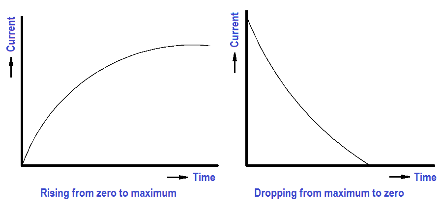
Figure 6 : DC Current Through an Inductor

The relationship between values of current reached and the time it takes to reach them is called a time constant. The time constant for an inductor is defined as the time required for the current either to increase to 63.2 percent of its maximum value or to decrease by 63.2 percent of its maximum value (Figure 7).

Inductive Time Constant

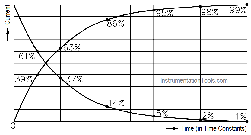
Figure 7 : Time Constant

The value of the time constant is directly proportional to the inductance and inversely proportional to the resistance. If these two values are known, the time constant can be found using below Equation.

Inductance Time Constant Formula

where

TL = time constant (seconds)
L = inductance (henries)
R = resistance (ohms)

The voltage drop across an inductor is directly proportional to the product of the inductance and the time rate of change of current through the inductor, as shown in below Equation.

Inductor Voltage Drop Equation

where

VL = voltage drop across the inductor (volts)
L = inductance (henries)
∆I/∆t = time rate of change of current (amp/sec)

After five time constants, circuit parameters normally reach their final value. Circuits that contain both inductors and resistors are called RL circuits.

The following example will illustrate how an RL circuit reacts to changes in the circuit (Figure 8).

RL Circuit Time Constant

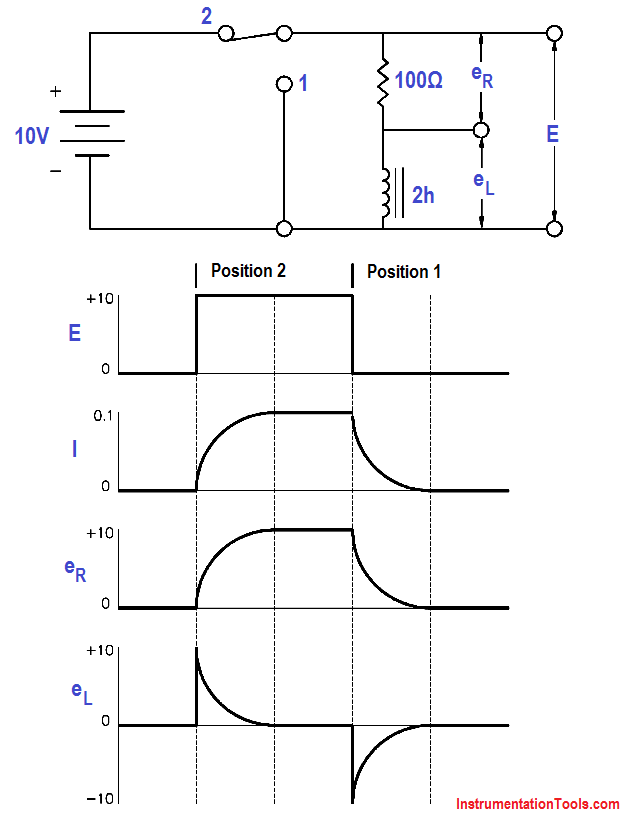
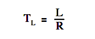
Figure 8 : Voltage Applied to an Inductor

1. Initially, the switch is in Position 1, and no current flows through the inductor.

2. When we move the switch to Position 2, the battery attempts to force a current of 10v/100Ω = 0.1A through the inductor. But as current begins to flow, the inductor generates a magnetic field. As the field increases, a counter EMF is induced that opposes the battery voltage. As a steady state is reached, the counter EMF goes to zero exponentially.

3. When the switch is returned to Position 1, the magnetic field collapses, inducing an EMF that tends to maintain current flow in the same direction through the inductor. Its polarity will be opposite to that induced when the switch was placed in Position 2.

The example that follows shows how a circuit with an inductor in parallel with a resistor reacts to changes in the circuit. Inductors have some small resistance, and this is shown schematically as a 1Ω resistor (Figure 9).

Inductor and Resistor in Parallel

Figure 9 : Inductor and Resistor in Parallel

1. While the switch is closed, a current of 20 v/1Ω = 20 amps flows through the inductor. This causes a very large magnetic field around the inductor.

2. When we open the switch, there is no longer a current through the inductor. As the magnetic field begins to collapse, a voltage is induced in the inductor. The change in applied voltage is instantaneous; the counter EMF is of exactly the right magnitude to prevent the current from changing initially. In order to maintain the current at 20 amps flowing through the inductor, the self-induced voltage in the inductor must be enough to push 20 amps through the 101Ω of resistance. The CEMF = (101)(20) = 2020 volts.

3. With the switch open, the circuit looks like a series RL circuit without a battery. The CEMF induced falls off, as does the current, with a time constant TL of:

Inductance Time Constant Formula

TL = 4h/101 Ω = 0.039 sec

Don't Miss Our Updates
Be the first to get exclusive content straight to your email.
We promise not to spam you. You can unsubscribe at any time.
Invalid email address
You've successfully subscribed !
4-Wire, Three-Phase Wye Wiring System
Induction Motor
Power Triangle
Electro-Dynamo Meter Movement
Batteries
Share This Article
Facebook Whatsapp Whatsapp LinkedIn Copy Link
Share
Leave a Comment

Leave a Reply Cancel reply

Your email address will not be published. Required fields are marked *

Stay Connected

128.3kFollowersLike
69.1kFollowersFollow
208kSubscribersSubscribe
38kFollowersFollow

Categories

Recent Comments

  • Guifty Shimica on Top Non-PLC Certification Courses for Automation Professionals
  • Guifty Shimica on Top Non-PLC Certification Courses for Automation Professionals
  • MIHARITSOA Aina Sitraka on Top Non-PLC Certification Courses for Automation Professionals
  • Vaishnavi on Free Instrumentation Course for Trainee Engineers

Related Articles

Voltage and Current Phase Relationships in an Inductive Circuit

Voltage and Current Phase Relationships in an Inductive Circuit

Parallel RLC Circuit

Resonance, Resonant Frequency, Series and Parallel Resonance

induction motor torque versus speed

Induction Motor Torque Versus Slip

Compounded DC Generator

Parallel AC Generators

Basic AC Generator

AC Generator Parts

Using Kirchhoff’s Voltage Law to find Current with Multiple Battery Sources

Kirchhoff’s Laws

Capacitor and Symbols

Capacitance

Series - Wound DC Motor

Series-Wound Motor

More Articles

Advantages and Disadvantages of Network Topology

Advantages and Disadvantages of Per Unit System

Things to Take Care of When Designing SCADA System

Things to Take Care of When Designing SCADA System

What Do You Learn in Software Engineering

What Do You Learn in Software Engineering?

Siemens Tia Portal PLC Training Course

Siemens Tia Portal PLC Training Course

oxygen Safety Analyzer

Oxygen Safety Analyzer

Digital Electronics MCQ

Sum of Products & Products of Sum Objective Questions

Two SOV Connections

Two Solenoid Valves Working Principle

Types of Can Open network topologies

CANOpen Network Topology

Follow US
All rights reserved. Reproduction in whole or in part without written permission is prohibited.
Welcome Back!

Sign in to your account

Username or Email Address
Password

Lost your password?