Inst ToolsInst ToolsInst Tools
  • Ask
  • Courses
  • Videos
  • Q & A
    • Interview
      • Instrumentation
      • Electronics
      • Electrical
      • Practical Questions
    • MCQ
      • Instrumentation MCQ
      • Electrical MCQ
      • Electronics MCQ
      • Control Systems MCQ
      • Analog Electronics MCQ
      • Digital Electronics MCQ
      • Power Electronics MCQ
      • Microprocessor MCQ
      • Multiple Choice Questions
  • EE
    • Electronics
      • Electronics Q & A
      • Electronic Basics
      • Electronic Devices & Circuits
      • Electronics Animation
      • Digital Electronics
    • Electrical
      • Electrical Basics
      • Electrical Q & A
      • Power Electronics
      • Electrical Machines
      • Electrical Animation
      • Power Systems
      • Switchgear & Protection
      • Transmission & Distribution
  • Measure
    • Control Valves
    • Calibration
    • Temperature
    • Pressure
    • Flow
    • Level
    • Analyzers
    • Switches
    • Vibration
    • Solenoid Valve
  • Control
    • PLC Tutorials
    • Control Systems
    • Safety Instrumented System (SIS)
    • Communication
    • Fire & Gas System
  • More
    • Design
    • Tools
    • Animation
    • Basics
    • Formulas
    • Standards
    • TextBooks
    • Common
    • Software
    • Excel Tools
    • Erection & Commissioning
    • Process Fundamentals
    • Videos
    • Books
Search
All rights reserved. Reproduction in whole or in part without written permission is prohibited.
Reading: Y and Delta Resistor Network Calculations
Share
Notification Show More
Font ResizerAa
Inst ToolsInst Tools
Font ResizerAa
  • Courses
  • PLC Tutorials
  • Control Systems
Search
  • Ask
  • Courses
  • Videos
  • Q & A
    • Interview
    • MCQ
  • EE
    • Electronics
    • Electrical
  • Measure
    • Control Valves
    • Calibration
    • Temperature
    • Pressure
    • Flow
    • Level
    • Analyzers
    • Switches
    • Vibration
    • Solenoid Valve
  • Control
    • PLC Tutorials
    • Control Systems
    • Safety Instrumented System (SIS)
    • Communication
    • Fire & Gas System
  • More
    • Design
    • Tools
    • Animation
    • Basics
    • Formulas
    • Standards
    • TextBooks
    • Common
    • Software
    • Excel Tools
    • Erection & Commissioning
    • Process Fundamentals
    • Videos
    • Books
Follow US
All rights reserved. Reproduction in whole or in part without written permission is prohibited.
Inst Tools > Blog > Electrical Theory > Y and Delta Resistor Network Calculations

Y and Delta Resistor Network Calculations

Last updated: July 25, 2018 7:20 pm
Editorial Staff
Electrical Theory
No Comments
Share
3 Min Read
SHARE

Because of its shape, the network shown in Figure 47 is called a T (tee) or Y (wye) network.

These are different names for the same network.
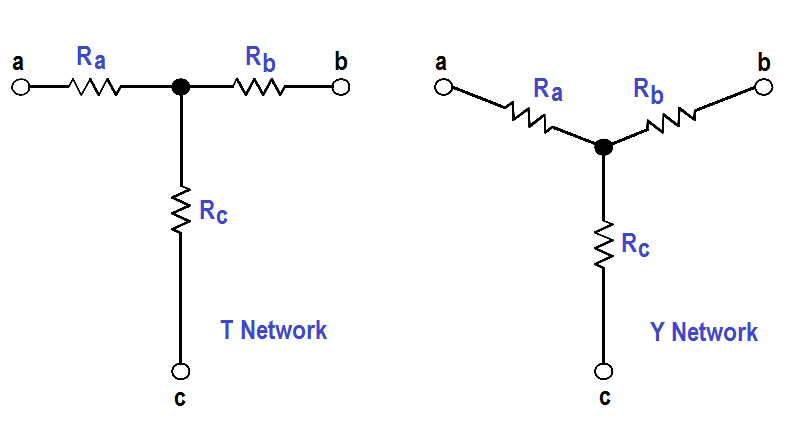
T or Y Network

Figure 47 : T or Y Network

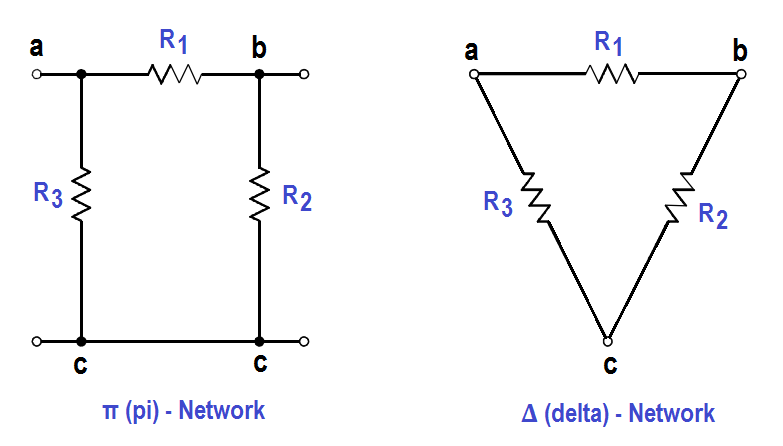
The network shown in Figure 48 is called π (pi) or ∆ (delta) because the shapes resemble Greek letters π and Ω. These are different names for the same network.

π (pi) or ∆ (delta) Network

Figure 48 : π (pi) or ∆ (delta) Network

In order to analyze the circuits, it may be helpful to convert Y to ∆,or ∆ to Y, to simplify the solution. The formulas that will be used for these conversions are derived from Kirchhoff’s laws.

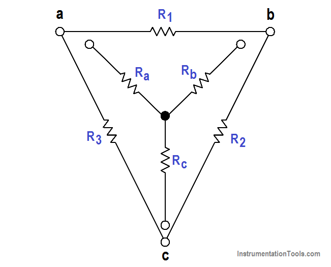
The resistances in these networks are shown in a three-terminal network. After we use the conversion formulas, one network is equivalent to the other because they have equivalent resistances across any one pair of terminals (Figure 49).

∆ to Y conversion:

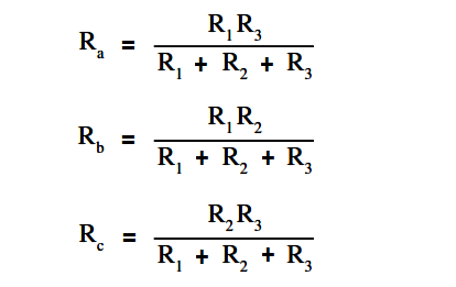
∆ to Y conversion Formulas

Rule 1: The resistance of any branch of a Y network is equal to the product of the two adjacent sides of a ∆ network, divided by the sum of the three ∆ resistances.

Y - ∆ Equivalent of Resistor Network

Figure 49 : Y – ∆ Equivalent

Y to ∆ conversion:

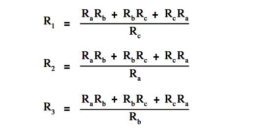
Y - ∆ Equivalent of Resistor network formula

Rule 2: The resistance of any side of a ∆ network is equal to the sum of the Y network resistance, multiplied in pairs, divided by the opposite branch of the Y network.

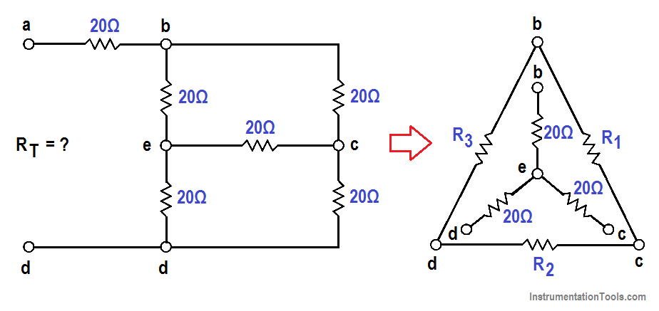
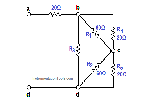
Let us consider a bridge circuit (Figure 50).

Resistor Delta Network

Figure 50 : Bridge Circuit

Find Rt at terminals a and d.

Step 1: Convert the Y network (b-e, e-c, e-d) to the equivalent ∆ network.

Using Rule 2:

R1 = { (20×20) + (20×20) + (20×20) } / 20 = 1200/20 = 60Ω

R2 = 1200/20 = 60Ω

R3 = 1200/20 = 60Ω

Step 2: Now, we can redraw the Y circuit as a ∆ circuit and reconnect it to the original circuit (Figure 51):

Y - ∆ Redrawn Resistor Circuit

Figure 51 : Y – ∆ Redrawn Circuit

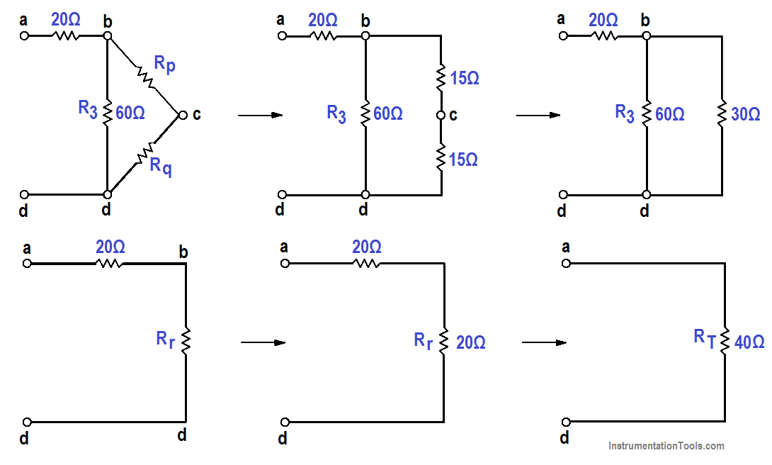
Step 3: Reduce and simplify the circuit. Note that the 20Ω and 60Ω branches are in parallel in Figure 51. Refer to Figures 51 and 52 for redrawing the circuit in each step below.

Rp = (R1R4) / (R1 + R4) = (20×60) / (20+60) = 1200/80 = 15Ω

Rq = (R1R5) / (R1 + R5) = (20×60) / (20+60) = 1200/80 = 15Ω

Rr = [ R3(Rp + Rq) ] / [R3 +Rp+Rq] = [60x(15+5)] / [60+30] = 1800/90 = 20Ω

RT = 20 + 20 = 40Ω

Resistor Y and Delta Network Calculation

Figure 52 : Steps to Simplify Redrawn Circuit
Don't Miss Our Updates
Be the first to get exclusive content straight to your email.
We promise not to spam you. You can unsubscribe at any time.
Invalid email address
You've successfully subscribed !
Moving Iron Vane Meter Movement
Voltage Polarity and Current Direction
AC Generation
Apparent Power, True Power, Reactive Power & Total Power
AC Induction Motor Slip
Share This Article
Facebook Whatsapp Whatsapp LinkedIn Copy Link
Share
Leave a Comment

Leave a Reply Cancel reply

Your email address will not be published. Required fields are marked *

Stay Connected

128.3kFollowersLike
69.1kFollowersFollow
208kSubscribersSubscribe
38kFollowersFollow

Categories

Recent Comments

  • Kamli on Top Free PLC Software
  • Guifty Shimica on Top Non-PLC Certification Courses for Automation Professionals
  • Guifty Shimica on Top Non-PLC Certification Courses for Automation Professionals
  • MIHARITSOA Aina Sitraka on Top Non-PLC Certification Courses for Automation Professionals

Related Articles

Voltage Drop in a Series Circuit

Series Resistance

Single Line Diagram

Single Line Diagram

Three Phase To Single Phase Wiring Connections

Single Phase Power Wiring Schemes

Electrical Symbols

Electrical Symbols

Types of Batteries

Types of Batteries

Potential Difference Across a Conductor Causes a Current to Flow

Conductor, Insulator, Resistor and Current Flow

Calculate Power in Parallel RC Circuit

Calculate Power in Parallel RC Circuit

Marking Polarity

DC Circuit Analysis Loop Equations

More Articles

Transmitter Proof Testing

Transmitter Proof Testing

D’Arsonval Movement

D’Arsonval Movement

Open Loop and Closed Loop System Questions

Open Loop and Closed Loop System Questions Answers

Emergency Shutdown System Philosophy

Shutdown Philosophy

pn-junction-with-depletion-layer

How a PN Junction Formed in a Diode

Process-Variable-to-Percentage-Conversion

Formula for Process Variable to Percentage Conversion

Fieldbus Wiring

Fieldbus vs 4-20mA

Electronic Devices & Circuits Objective Questions

Electronic Devices & Circuits Quiz – Set 11

Follow US
All rights reserved. Reproduction in whole or in part without written permission is prohibited.
Welcome Back!

Sign in to your account

Username or Email Address
Password

Lost your password?