Inst ToolsInst ToolsInst Tools
  • Courses
  • Automation
    • PLC
    • Control System
    • Safety System
    • Communication
    • Fire & Gas System
  • Instrumentation
    • Design
    • Pressure
    • Temperature
    • Flow
    • Level
    • Vibration
    • Analyzer
    • Control Valve
    • Switch
    • Calibration
    • Erection & Commissioning
  • Interview
    • Instrumentation
    • Electrical
    • Electronics
    • Practical
  • Q&A
    • Instrumentation
    • Control System
    • Electrical
    • Electronics
    • Analog Electronics
    • Digital Electronics
    • Power Electronics
    • Microprocessor
Search
  • Books
  • Software
  • Projects
  • Process
  • Tools
  • Basics
  • Formula
  • Power Plant
  • Root Cause Analysis
  • Electrical Basics
  • Animation
  • Standards
  • 4-20 mA Course
  • Siemens PLC Course
Reading: Parallel Circuit Current Calculations
Share
Notification Show More
Font ResizerAa
Inst ToolsInst Tools
Font ResizerAa
  • Courses
  • Design
  • PLC
  • Interview
  • Control System
Search
  • Courses
  • Automation
    • PLC
    • Control System
    • Safety System
    • Communication
    • Fire & Gas System
  • Instrumentation
    • Design
    • Pressure
    • Temperature
    • Flow
    • Level
    • Vibration
    • Analyzer
    • Control Valve
    • Switch
    • Calibration
    • Erection & Commissioning
  • Interview
    • Instrumentation
    • Electrical
    • Electronics
    • Practical
  • Q&A
    • Instrumentation
    • Control System
    • Electrical
    • Electronics
    • Analog Electronics
    • Digital Electronics
    • Power Electronics
    • Microprocessor
Follow US
All rights reserved. Reproduction in whole or in part without written permission is prohibited.
Inst Tools > Blog > Electrical Theory > Parallel Circuit Current Calculations

Parallel Circuit Current Calculations

Last updated: July 23, 2018 12:57 pm
Editorial Staff
Electrical Theory
No Comments
Share
2 Min Read
SHARE

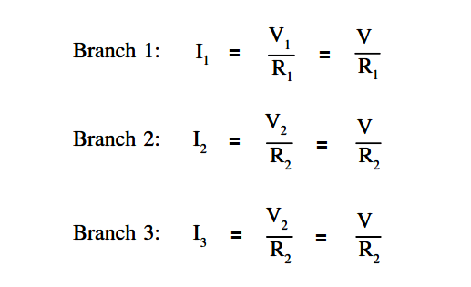
The sum of the currents flowing through each branch of a parallel circuit is equal to the total current flow in the circuit.

Parallel Circuit

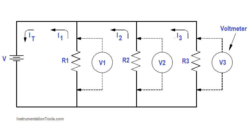
Using Ohm’s Law, the branch current for a three branch circuit equals the applied voltage divided by the resistance as shown in below equations.

Parallel Circuit Parallel Current Calculations

Example 1:

Two resistors, each drawing 3A, and a third resistor, drawing 2A, are connected in parallel across a 115 volt source (Figure 23). What is total current?

Parallel Resistance Circuit Current Calculations

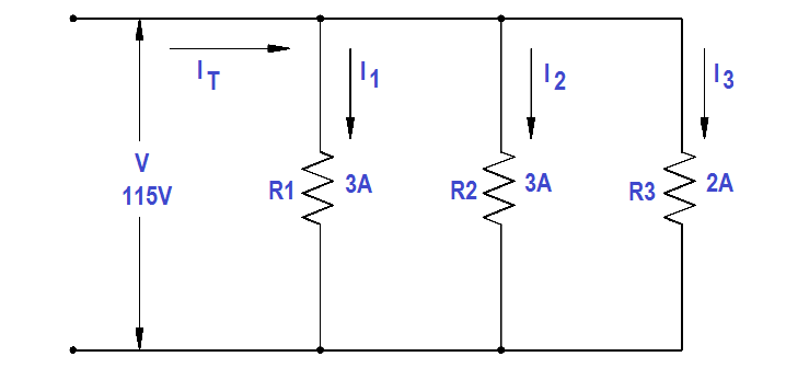
Figure 23 Example 1 Parallel Circuit

IT = I1 + I2 + I3

IT = 3 + 3 + 2 = 8 A

Example 2:

Two branches, R 1 and R2 , are across a 120 V power source. The total current flow is 30 A (Figure 24). Branch R1 takes 22 amps. What is the current flow in Branch R2 ?

Parallel Circuit Current Flow Calculations

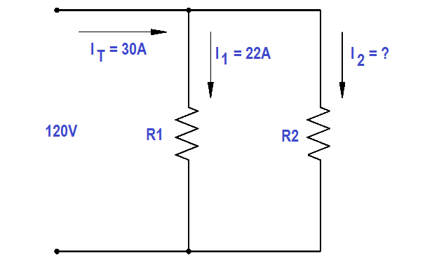
Figure 24 Example 2 Parallel Circuit

Solution :

IT = I1 + I2

I2 = IT – I1

I2 = 30 -22 = 8A

Example 3:

A parallel circuit consists of R1 =15Ω, R2 =20Ω and R3 =10Ω, with an applied voltage of 120 V (Figure 25). What current will flow through each branch?

Parallel Circuit Current Equation

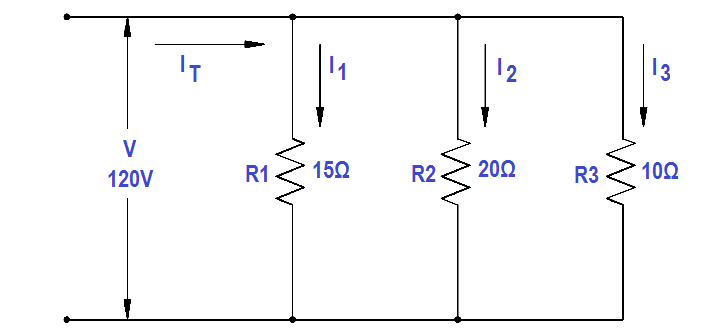
Figure 25 Example 3 Parallel Circuit

Solution :

I1 = V/R1 = 120/15 = 8A

I2 = V/R2 = 120/20 = 6A

I3 = V/R3 = 120/10 = 12A

IT = I1 + I2 + I3 

IT = 8 + 6+ 12 = 26 A

Don't Miss Our Updates
Be the first to get exclusive content straight to your email.
We promise not to spam you. You can unsubscribe at any time.
Invalid email address
You've successfully subscribed !

Continue Reading

Power Factor Meter Principle
Series Short Circuit Faults
Impedance in RC Circuits
Ohm Meter
Conductor, Insulator, Resistor and Current Flow
Transformer Coil Polarity
Share This Article
Facebook Whatsapp Whatsapp LinkedIn Copy Link
Share
Leave a Comment

Leave a Reply Cancel reply

Your email address will not be published. Required fields are marked *

Stay Connected

128.3kFollowersLike
69.1kFollowersFollow
208kSubscribersSubscribe
38kFollowersFollow

Categories

Explore More

Power Factor
Circuit Breaker Control Circuit
Series and Parallel Capacitors
Batteries
Resonance, Resonant Frequency, Series and Parallel Resonance
Impedance in RL Circuits
DC Circuit Analysis Loop Equations
DC Motor Torque

Keep Learning

Ammeter with Shunt

Ammeter

Transformer Efficiency and Loses Formula

Transformer Losses and Efficiency

current division Formula for Resistor Circuit

Current Division

Total Resistance in a Parallel Circuit

Resistance in Parallel Circuits

DC Machine

DC Machines Construction

Using Kirchhoff’s Voltage Law to find Current with one Source

Applying Kirchhoff’s Voltage Law

Calculate Power in Series RL Circuit

Calculate Power in Series RL Circuit

Single Phase Motor Manual Controller

Motor Controllers

Learn More

De-energized Electrical Circuits

De-energized Electrical Circuits, Networks, and Equipment

Junction Box Wiring

4-20mA Junction Box versus Fieldbus (FF) Junction Box

DP-Transmitter-with-two-seals

DP Transmitter with Two Seals applications

Analyzers Questions and Answers

Electron Probe Microanalyser Questions & Answers

Flapper nozzle system

What is Flapper Nozzle System ?

Calibration Standards

Practical Calibration Standards

5 Tips to Pass CFSE Exam

5 Tips to Pass CFSE Exam

Microprocessors Objective Questions

Microprocessors Objective Questions – Set 2

Follow US
All rights reserved. Reproduction in whole or in part without written permission is prohibited.
Welcome Back!

Sign in to your account

Username or Email Address
Password

Lost your password?