Inst ToolsInst ToolsInst Tools
  • Courses
  • Automation
    • PLC
    • Control System
    • Safety System
    • Communication
    • Fire & Gas System
  • Instrumentation
    • Design
    • Pressure
    • Temperature
    • Flow
    • Level
    • Vibration
    • Analyzer
    • Control Valve
    • Switch
    • Calibration
    • Erection & Commissioning
  • Interview
    • Instrumentation
    • Electrical
    • Electronics
    • Practical
  • Q&A
    • Instrumentation
    • Control System
    • Electrical
    • Electronics
    • Analog Electronics
    • Digital Electronics
    • Power Electronics
    • Microprocessor
  • Request
Search
  • Books
  • Software
  • Projects
  • Process
  • Tools
  • Basics
  • Formula
  • Power Plant
  • Root Cause Analysis
  • Electrical Basics
  • Animation
  • Standards
  • 4-20 mA Course
  • Siemens PLC Course
Reading: D.C Tachogenerator Principle
Share
Notification Show More
Font ResizerAa
Inst ToolsInst Tools
Font ResizerAa
  • Courses
  • Design
  • PLC
  • Interview
  • Control System
Search
  • Courses
  • Automation
    • PLC
    • Control System
    • Safety System
    • Communication
    • Fire & Gas System
  • Instrumentation
    • Design
    • Pressure
    • Temperature
    • Flow
    • Level
    • Vibration
    • Analyzer
    • Control Valve
    • Switch
    • Calibration
    • Erection & Commissioning
  • Interview
    • Instrumentation
    • Electrical
    • Electronics
    • Practical
  • Q&A
    • Instrumentation
    • Control System
    • Electrical
    • Electronics
    • Analog Electronics
    • Digital Electronics
    • Power Electronics
    • Microprocessor
  • Request
Follow US
All rights reserved. Reproduction in whole or in part without written permission is prohibited.
Inst Tools > Blog > Common > D.C Tachogenerator Principle

D.C Tachogenerator Principle

Last updated: April 1, 2018 12:01 pm
Editorial Staff
Common
No Comments
Share
2 Min Read
SHARE

The D.C Tachogenerators is a type of electrical type’s tachogenerators which can also be used for speed measurement.

The D.C tachogenerator is shown in below figure.

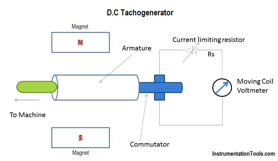
The armature of the D.C Tachogenerator is kept in the permanent magnetic field. The armature of the tachogenerator is coupled to the machine whose speed is to be measured. When the shaft of the machine revolves, the armature of the tachogenerator revolves in the magnetic field producing e.m.f. which is proportional to the product of the flux and speed to be measured.

Now as the field of the permanent field is fixed, the e.m.f generated is proportional to the speed directly. The e.m.f induced is measured using moving coil voltmeter with uniform scale calibrated in speed directly. The series resistance is used to limit the current under output short circuit condition. The polarity of output voltage indicates the direction of rotation. The commutator collects current from armature conductors and converts internally induced a.c e.m.f into d.c (unidirectional) e.m.f. while the brushes are used to collect current from commutator and make it available to external circuitry of the d.c tachogenerator.

D.C Tachogenerator Principle

Advantages

The advantages of d.c tachogenerator are as follows:

1.The output voltage is small enough to measure it with conventional d.c voltmeters.
2.The polarity of output voltage directly indicates the direction of rotation.

Disadvantages

The Disadvantages of d.c tachogenerator are as follows:

1.Because of variations in contact resistance, considerable error is introduced in the output voltage. Hence periodic maintenance of the commutator and brushes is required.

2.Non-linearity in the output of the d.c tachogenerator occurs because of distortions in the permanent magnetic field due to large armature currents. Hence input resistance of meter should be very high as compared to the output resistance of the generator.

Don't Miss Our Updates
Be the first to get exclusive content straight to your email.
We promise not to spam you. You can unsubscribe at any time.
Invalid email address
You've successfully subscribed !

Continue Reading

Why Using VoIP Systems Can Save You and Your Business Money?
Mechanical Torsion Meter Principle
Different Types of Sensors used in Automotive Vehicles
What is VoIP and How Does it Work? Advantages & applications
Types of Angular Velocity Measurement
Loop diagram and System Inspection Lab Exercise
Share This Article
Facebook Whatsapp Whatsapp LinkedIn Copy Link
Share
Leave a Comment

Leave a Reply Cancel reply

Your email address will not be published. Required fields are marked *

Stay Connected

128.3kFollowersLike
69.1kFollowersFollow
210kSubscribersSubscribe
38kFollowersFollow

Categories

Explore More

Why do Teenagers want to be Entrepreneurs?
List of Tools used by Instrument Technician or Engineer
What Type of Heating is Best for Your Home?
Introduction to Wastewater Treatment Works and Pumping Station
Slip Rings in Robotics – Types, Applications, Advantages
What is a Database Server? – Types, Comparison
Advantages and Disadvantages of Pneumatic Instruments
Know the Best Path to Achieve SOA-C02 Exam Certification

Keep Learning

Reproducibility in Measurement

What is Reproducibility?

Self-balancing Pneumatic Instrument Principles - 3

Self-balancing Pneumatic Instrument Principles

Top 100 Microcontrollers Project Ideas

Top 100 Microcontrollers Project Ideas

temperature sensor

Dead time

refrigeration compressors

Why is CO2 the Most Promising Refrigerant in Cooling Industry?

What is PDCA - Industrial Maintenance

What is PDCA? – Industrial Maintenance

CNC Machine Tools Problems and Solutions

Common Problems With CNC Machine Tools & Their Solutions

Discrete Manufacturing Automation

Discrete Manufacturing Automation

Learn More

Contacting Radar Tank Gauges

Radar Tank Gauging

RF-Capacitance Level Switch Principle

RF Capacitance Level Switch Working Principle

SCADA in Power System

Electrical Energy Management System and SCADA in Power System

Most Common Types of Cyber Attacks

20 Most Common Types of Cyber Attacks

Motor Primary Resistance Starter

Electrical Motor Starter Circuits

Elevated Span and Suppressed Span

DP Level Transmitter Elevation and Suppression Corrections

What is Cavitation

What is Cavitation? What are the Causes?

Instrumentation Cables Armor

Instrumentation Cables Armor

Menu

  • About
  • Privacy Policy
  • Copyright

Quick Links

  • Learn PLC
  • Helping Hand
  • Part Time Job

YouTube Subscribe

Follow US
All rights reserved. Reproduction in whole or in part without written permission is prohibited.
Welcome Back!

Sign in to your account

Username or Email Address
Password

Lost your password?