Nuclear fission is a process by which the nuclei of specific types of atoms (most notably uranium-235 and plutonium-239) undergo spontaneous disintegration upon the absorption of an extra neutron, with the release of significant thermal energy and additional neutrons.
A quantity of fissile material subjected to a source of neutron particle radiation will begin to fission, releasing massive quantities of heat which may then be used to boil water into steam and drive steam turbine engines to generate electricity.
The “chain reaction” of neutrons splitting fissile atoms, which then eject more neutrons to split more fissile atoms, is inherently exponential in nature, but may be regulated by natural and artificial feedback loops.
SIS Example : Nuclear Reactor Controls
A simplified diagram of a pressurized water reactor (PWR) appears here:

In the United States of America, nuclear reactors are designed to exhibit what is called a negative temperature coefficient, which means the chain reaction naturally slows as the temperature of the coolant increases.
This physical tendency, engineered by the configuration of the reactor core and the design of the coolant system, adds a measure of self-stabilization to what would otherwise be an inherently unstable (“runaway”) process.
This is an example of a “natural” negative-feedback loop in action: a process by which the very laws of physics conspire to regulate the activity of the fission reaction.
Additional regulation ability comes from the insertion of special control rods into the reactor core, designed to absorb neutrons and prevent them from “splitting” more atoms.
With enough control rods inserted into a reactor core, a chain reaction cannot self-sustain. With enough control rods withdrawn from a freshly-fueled reactor core, the chain reaction will grow to an intensity strong enough to damage the reactor.
Control rod position thus constitutes the primary method of power control for a fission reactor, and also the first means of emergency shutdown. These control rods are inserted and withdrawn in order to exert demand-control over the fission reaction.
If the reaction rate is too low to meet demand, either a human operator or an automatic control system may withdraw the rods until the desired reactivity is reached. If the reaction rate becomes excessive, the rods may be inserted until the rate falls down to the desired level.
Control rods are therefore the final control element (FCE) of an “artificial” negative-feedback loop designed to regulate reaction rate at a level matching power demand.
Due to the intense radiation flux near an operating power reactor, these control rods must be manipulated remotely rather than by direct human actuation. Nuclear reactor control rod actuators are typically special electric motors developed for this critical application.
A photograph showing the control rod array at the top of the ill-fated reactor at Three-Mile Island nuclear power plant appears here, with a mass of control cables connecting the rod actuators to the reactor control system:

Rapid insertion of control rods into a reactor core for emergency shutdown purposes is called a scram. Accounts vary as to the origin of this term, whether it has meaning as a technical acronym or as a colloquial expression to evacuate an area. Regardless of its etymology, a “scram” is an event to be avoided if possible.
Like all industrial processes, a nuclear reactor fulfills its intended purpose only when operating. Shutdowns represent not only loss of revenue for the operating company, but also loss of power to local utilities and possible disruption of critical public services (heating, cooling, water pumping, fire protection, traffic control, etc.).
An emergency shutdown system at a nuclear power plant must fulfill the opposing roles of dependability and security, with an extremely high degree of instrument reliability.
The electric motor actuators intended for normal operation of control rods are generally too slow to use for scram purposes. Hydraulic actuators capable of overriding the electric motor actuation may be used for scram insertion.
Some early pressurized-water reactor scram system designs used a simple mechanical latch, disengaging the control rods from their motor actuators and letting gravity draw the rods fully into the reactor core.
A partial list of criteria sufficient to initiate a reactor scram is shown here:
- Detected earthquake
- Reactor pressure high
- Reactor pressure low
- Reactor water level low (BWR only)
- Reactor differential temperature high
- Main steam isolation valve shut
- Detected high radioactivity in coolant loop
- Detected high radioactivity in containment building
- Manual shutdown switch(es)
- Control system power loss
- Core neutron flux high
- Core neutron flux rate-of-change (period) high
The last two criteria bear further explanation. Since each fission event (the “splitting” of one fuel atom’s nucleus by an absorbed neutron) results in a definite amount of thermal energy release and also a definite number of additional neutrons released, the number of neutrons detected in the reactor core at any given moment is an approximate indication of the core’s thermal power as well as its reactivity.
Neutron radiation flux measurement is therefore a fundamental process variable for fission reactor control, and also for safety shutdown. If sensors detect an excessive neutron flux, the reactor should be “scrammed” to avoid damage due to overheating.
Likewise, if sensors detect a neutron flux level that is rising at an excessive rate, it indicates the possibility of a runaway chain-reaction which should also initiate a reactor “scram.”
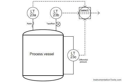
In keeping with the high level of reliability and emphasis on safety for nuclear reactor shutdown controls, a common redundant strategy for sensors and logic is two-out-of-four, or 2oo4.
A contact logic diagram showing a 2oo4 configuration appears here: