Inst ToolsInst ToolsInst Tools
  • Ask
  • Courses
  • Videos
  • Q & A
    • Interview
      • Instrumentation
      • Electronics
      • Electrical
      • Practical Questions
    • MCQ
      • Instrumentation MCQ
      • Electrical MCQ
      • Electronics MCQ
      • Control Systems MCQ
      • Analog Electronics MCQ
      • Digital Electronics MCQ
      • Power Electronics MCQ
      • Microprocessor MCQ
      • Multiple Choice Questions
  • EE
    • Electronics
      • Electronics Q & A
      • Electronic Basics
      • Electronic Devices & Circuits
      • Electronics Animation
      • Digital Electronics
    • Electrical
      • Electrical Basics
      • Electrical Q & A
      • Power Electronics
      • Electrical Machines
      • Electrical Animation
      • Power Systems
      • Switchgear & Protection
      • Transmission & Distribution
  • Measure
    • Control Valves
    • Calibration
    • Temperature
    • Pressure
    • Flow
    • Level
    • Analyzers
    • Switches
    • Vibration
    • Solenoid Valve
  • Control
    • PLC Tutorials
    • Control Systems
    • Safety Instrumented System (SIS)
    • Communication
    • Fire & Gas System
  • More
    • Design
    • Tools
    • Animation
    • Basics
    • Formulas
    • Standards
    • TextBooks
    • Common
    • Software
    • Excel Tools
    • Erection & Commissioning
    • Process Fundamentals
    • Videos
    • Books
Search
All rights reserved. Reproduction in whole or in part without written permission is prohibited.
Reading: What is Control Valve Flashing ?
Share
Notification Show More
Font ResizerAa
Inst ToolsInst Tools
Font ResizerAa
  • Courses
  • PLC Tutorials
  • Control Systems
Search
  • Ask
  • Courses
  • Videos
  • Q & A
    • Interview
    • MCQ
  • EE
    • Electronics
    • Electrical
  • Measure
    • Control Valves
    • Calibration
    • Temperature
    • Pressure
    • Flow
    • Level
    • Analyzers
    • Switches
    • Vibration
    • Solenoid Valve
  • Control
    • PLC Tutorials
    • Control Systems
    • Safety Instrumented System (SIS)
    • Communication
    • Fire & Gas System
  • More
    • Design
    • Tools
    • Animation
    • Basics
    • Formulas
    • Standards
    • TextBooks
    • Common
    • Software
    • Excel Tools
    • Erection & Commissioning
    • Process Fundamentals
    • Videos
    • Books
Follow US
All rights reserved. Reproduction in whole or in part without written permission is prohibited.
Inst Tools > Blog > Control Valves > What is Control Valve Flashing ?

What is Control Valve Flashing ?

Last updated: February 5, 2019 12:29 pm
Editorial Staff
Control Valves
1 Comment
Share
6 Min Read
SHARE

When a fluid passes through the constrictive passageways of a control valve, its average velocity increases.

Contents
ρ1A1v1 = ρ2A2v2Articles You May Like :Valves Multiple Choice QuestionsPilot-operated Safety & Relief ValvesGlobe Valve versus Gate ValveControl Valve Working AnimationControl Valve Tips & Tricks

This is predicted by the Law of Continuity, which states that the product of fluid density (ρ), cross-sectional area of flow (A), and average velocity (v) must remain constant for any flowstream:

ρ1A1v1 = ρ2A2v2

As fluid velocity increases through the constrictive passages of a control valve, the fluid molecules’ kinetic energy increases. In accordance with the Law of Energy Conservation, potential energy in the form of fluid pressure must decrease correspondingly.

Thus, fluid pressure decreases within the constriction of a control valve’s trim as it throttles the flow, then increases (recovers) after leaving the constrictive passageways of the trim and entering the wider areas of the valve body:

Control Valve Flashing

If the fluid being throttled by the valve is a liquid (as opposed to a gas or vapor), and its absolute pressure ever falls below the vapor pressure (Note) of that substance, the liquid will begin to boil.

This phenomenon, when it happens inside a control valve, is called flashing. As the graph shows, the point of lowest pressure inside the valve (called the vena contracta pressure, or Pvc) is the location where flashing will first occur, if it occurs at all.

Note : It should be noted that vapor pressure is a strong function of temperature. The warmer a liquid is, the more vapor pressure it will exhibit and thus the more prone it will be to flashing within a control valve.

Flashing is almost universally undesirable in control valves. The effect of boiling liquid at the point of maximum constriction is that flow through the valve becomes “choked” by the rapid expansion of liquid to vapor as it boils, degrading the valve’s flow capacity (i.e. decreasing the effective Cv).

Flashing is also destructive to the valve trim, as boiling action propels tiny droplets of liquid at extremely high velocities past the plug and seat faces, eroding the metal over time.

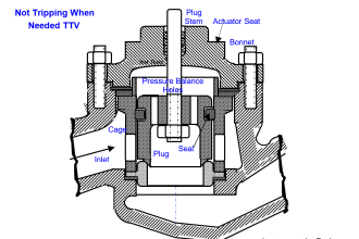
A photograph showing a severely eroded valve plug (from a cage-guided globe valve) reveals just how destructive flashing can be:

eroded valve plug

A characteristic effect of flashing in a control valve is a “hissing” sound, reminiscent of what sand might sound like if it were flowing through the valve.

An important parameter predicting flashing in a control valve is the valve’s pressure recovery factor, based on a comparison of the valve’s total pressure drop from inlet to outlet versus the pressure drop from inlet to the point of minimum pressure within the valve.

valve pressure recovery formula

Where,
FL = Pressure recovery factor (unitless)
P1 = Absolute fluid pressure upstream of the valve
P2 = Absolute fluid pressure downstream of the valve
Pvc = Absolute fluid pressure at the vena contracta (point of minimum fluid pressure within the valve)

The following set of illustrations shows three different control valves exhibiting the same permanent pressure drop (P1 − P2), but having different values of FL:

Control Valve pressure recovery

Valve #1 exhibits the greatest pressure recovery (i.e. the amount that fluid pressure increases from the minimum pressure at the vena contracta to the downstream pressure: P2 − Pvc) and the lowest FL value.

It is also the valve most prone to flashing in liquid service, because the vena contracta pressure is so much lower (all other factors being equal) than in the other two valves. If any of these valves will experience flashing in liquid service, it would be valve #1.

Valve #3, by contrast, has very little pressure recovery, and a large FL value (nearly equal to 1). From the perspective of avoiding flashing, it is the best of the three valves to use for liquid service.

The style of valve (ball, butterfly, globe, etc.) is very influential on pressure recovery factor. The more convoluted the path for fluid within a control valve, the more opportunities that fluid will have to dissipate energy in turbulent motion, resulting in the greatest permanent pressure drop for the least amount of restriction at any single point in the flow’s path.

Compare these two styles of valve to see which will have lowest pressure recovery factor and therefore be most prone to flashing:

Butterfly valve and Globe Valve

Clearly, the globe valve does a better job of evenly distributing pressure losses throughout the path of flow.

By contrast, the butterfly valve can only drop pressure at the points of constriction between the disk and the valve body, because the rest of the valve body is a straight-through path for fluid offering little restriction at all.

As a consequence, the butterfly valve experiences a much lower vena contracta pressure (i.e. greater pressure recovery, and a lower FL value) than the globe valve for any given amount of permanent pressure loss, making the butterfly valve more prone to flashing than the globe valve with all other factors being equal.

Articles You May Like :

Valves Multiple Choice Questions

Pilot-operated Safety & Relief Valves

Globe Valve versus Gate Valve

Control Valve Working Animation

Control Valve Tips & Tricks

Don't Miss Our Updates
Be the first to get exclusive content straight to your email.
We promise not to spam you. You can unsubscribe at any time.
Invalid email address
You've successfully subscribed !
Basic Parts of Control Valves
Working Principle of Hydraulic Actuators
Valve Basics, Sizing, and Actuators Books
How Gate Valves Work ?
Valve Seat Leakage Test
Share This Article
Facebook Whatsapp Whatsapp LinkedIn Copy Link
Share
1 Comment
  • Junaid says:
    August 23, 2018 at 12:50 am

    So excellent and informative

    Reply

Leave a Reply Cancel reply

Your email address will not be published. Required fields are marked *

Stay Connected

128.3kFollowersLike
69.1kFollowersFollow
208kSubscribersSubscribe
38kFollowersFollow

Categories

Recent Comments

  • Kamli on Top Free PLC Software
  • Guifty Shimica on Top Non-PLC Certification Courses for Automation Professionals
  • Guifty Shimica on Top Non-PLC Certification Courses for Automation Professionals
  • MIHARITSOA Aina Sitraka on Top Non-PLC Certification Courses for Automation Professionals

Related Articles

Types of Control Valves

Fundamentals of Valves and their Types

Internal Parts of Globe Valve

How to Choose a Control Valve?

Solenoid Valve Design

Solenoid Valve Selection Criteria

Direct Acting Control Valve Positioner

Pneumatic Valve Positioner Working Principle

JT Valve Working Principle

JT Valve Working Principle

control valve parts

Common Terms Used in Control Valves

Control Valve Passing Problem after Overhauling Job

Control Valve Passing Problem after Overhauling Job

Solenoid-Valve-Working-Animation

Solenoid Valve Working Animation

More Articles

Concept of Interlocking in PLC

Concept of Interlocking in PLC

Deep-Bed Filter

Deep-Bed Filters

Time Interval Measurement Objective Questions

Time Interval Measurement Objective Questions

PLC Structured Text Program for Light Sequences via Timers

PLC Structured Text Program for Light Sequences via Timers

GSD File installation in Simatic Manager

How to Install GSD File in Step 7 PLC using Simatic Manager?

Troubleshooting Pump Control Circuit

Troubleshooting Pump Control Circuit

Servo Operated Manometer Objective Questions

Servo Operated Manometer Objective Questions

Unbalanced 3 Phase Loads

Unbalanced 3 Phase Loads

Follow US
All rights reserved. Reproduction in whole or in part without written permission is prohibited.
Welcome Back!

Sign in to your account

Username or Email Address
Password

Lost your password?