A damper (otherwise known as a louvre) is a multi-element flow control device generally used to throttle large flows of air at low pressure.
Dampers find common application in furnace and boiler draft control, and in HVAC (Heating, Ventilation, and Air Conditioning) systems.
Common damper designs include parallel and radial. Parallel-vane dampers resemble a Venetian blind, with multiple rectangular vanes synchronously rotated to throttle flow through a rectangular opening.
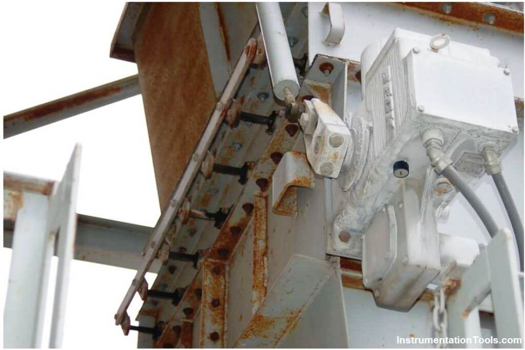
A photograph of a parallel-vane damper is shown here, part of an induced-draft (suction) air fan system on a separator at a cement plant.
The vanes are not visible in this photograph because they reside inside the metal air duct, but the actuator mechanism and linkages connecting seven vane shafts together are:
Dampers and Louvres
Dampers are available in motorized and gravity operated versions. Motorized (motor driven) dampers are typically used in applications where a very tight seal is required or when the damper has to operate against air pressure such as closing off a zone.
Gravity dampers are typically installed in the horizontal fan exhust applications. Vertical gravity dampers are commonly called shutters. Gravity dampers do not have motors and require air pressure/air flow to open.
Louvers are used on air intake or exhaust where protection from water infiltration is required. They have fixed blades that do not close so if the application requires air shutoff, a combination damper/louver is recommended.
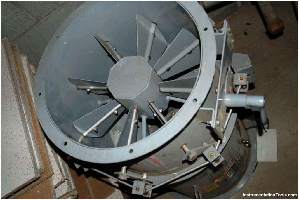
Radial-vane dampers use multiple vanes arranged like petals of a flower to throttle flow through a circular opening.
A photograph of a radial-vane damper is shown here (note the levers and linkages on the periphery of the tube, synchronizing the motions of the eight vanes so they rotate at the same angle):
Dampers find use in many non-industrial applications as well.
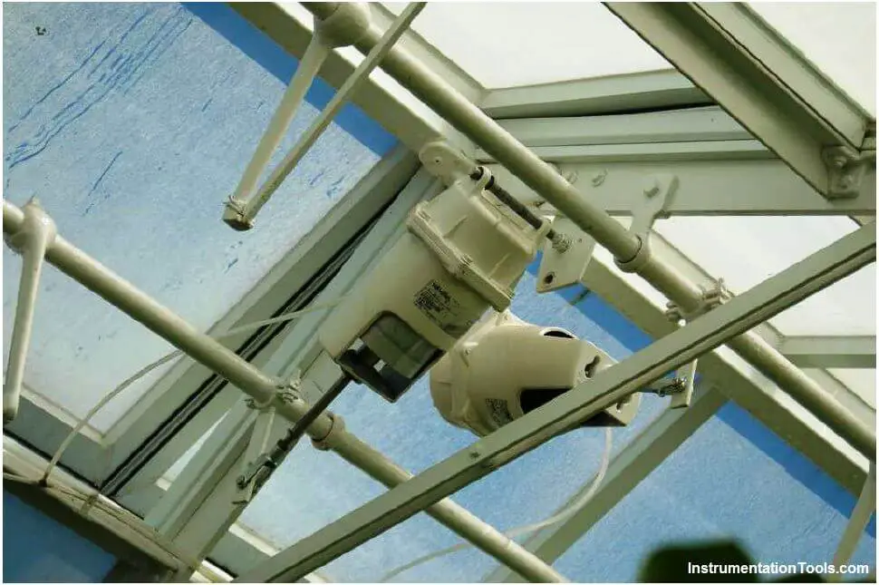
Take for instance these greenhouse vents, actuated by pneumatic (air-powered) piston actuators:
Also Read : Snap Acting Relay Principle
Types of Dampers and Louvers
Dampers are made of metal and usually square, circular, or rectangular in shape. Some industrial dampers are designed for pressure relief, or recommended for use within specific HVAC systems.
Like dampers, louvers are usually made of aluminum or steel. Louvers may be adjustable, or suitable for applications that require noise control.
Damper Types
Dampers are designated as industrial control, backdraft, counterbalanced, bubble tight, isolation, or discharge products.
- Backdraft dampers have a galvanized steel frame and extruded aluminum airfoil blades. These vanes provide improved strength with reduced noise and static pressure.
- Counterbalanced backdraft dampers are usually made of galvanized steel. They are designed to meet application requirements based on temperature, pressure, or velocity.
- Industrial dampers include bubble tight dampers, round isolation dampers, and round discharge dampers.
- Bubble tight dampers are used in applications that require shut-off capabilities under extreme conditions. They may be qualified for use in nuclear power plants and tested according to ASTM and ASME standards.
- Round isolation dampers are made of carbon steel and have a butterfly blade. They provide extremely low leakage in both HVAC and process systems.
- Round discharge dampers are also made of galvanized steel, but are designed for use on the discharge side of an axial flow fan. These dampers prevent fan shutdown and can withstand pressures and velocities in multi-fan applications.
Louver Types
There are four basic types of industrial louvers: stationary, adjustable, combination, and air measuring.
- Stationary louvers are equipped with angled or airfoil-style blades that may provide weather protection and sound attenuation.
- Adjustable louvers with airfoil blades are also commonly available.
- Combination louvers have blades that begin to open at one level of static pressure and become fully open at another. They may have backdraft damper blades and feature an all-aluminum construction for corrosion resistance.
- Air measuring louvers have closely-spaced vertical blades that prevent ingress of water.
Louvres vs. Dampers panels
Louvers are angled slats that allow the passage of air and light while dampers regulate the flow of air. Louvers and Dampers are mainly used in HVAC systems for the air flow, depending on the design requirement one can choose between dampers and louvers. Dampers can also block heat and smoke when used as smoke detectors.
- The main difference between Louvers and Dampers is that the blades of the louvers are constant and do not move while the blades of the Dampers move.
- The Louvers do not move hence they have no control over the regulation of air flow and release a standard flow of air while dampers are movable hence they act as a regulator to control the air flow.
- Both the dampers and louvers that are used in HVAC systems are usually made of aluminium or steel.
