A distributed control system (DCS) is a control system for a process plant in which autonomous controllers are distributed throughout the system.
A radically new concept appeared in the world of industrial control in the mid-1970’s: the notion of distributed digital control.
Direct digital control during that era suffered a substantial problem: the potential for catastrophic failure if the single digital computer executing multiple PID control functions were to ever halt.
Digital control brings many advantages, but it isn’t worth the risk if the entire operation will shut down (or catastrophically fail!) following a hardware or software failure within that one computer.
Distributed control directly addressed this concern by having multiple control computers – each one responsible for only a handful of PID loops – distributed throughout the facility and networked together to share information with each other and with operator display consoles.
With individual process control “nodes” scattered throughout the campus, each one dedicated to controlling just a few loops, there would be less concentration of liability as there would be with a single-computer DDC system.
Such distribution of computing hardware also shortened the analog signal wiring, because now the hundreds or thousands of analog field instrument cables only had to reach as far as the distributed nodes, not all the way to a centralized control room.
Only the networking cable had to reach that far, representing a drastic reduction in wiring needs.
Furthermore, distributed control introduced the concept of redundancy to industrial control systems: where digital signal acquisition and processing hardware units were equipped with “spare” units designed to automatically take over all critical functions in the event of a primary failure.
Distributed Control Systems (DCS)
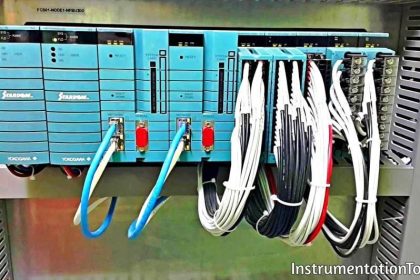
The following illustration shows a typical distributed control system (DCS) architecture:
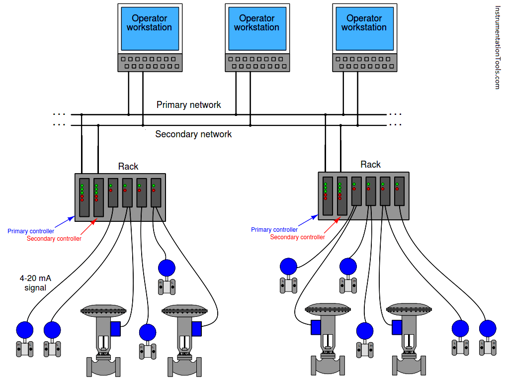
Each “rack” contains a microprocessor to implement all necessary control functions, with individual I/O (input/output) “cards” for converting analog field instrument signals into digital format, and vice-versa. Redundant processors, redundant network cables, and even redundant I/O cards address the possibility of component failure.
DCS processors are usually programmed to perform routine self-checks on redundant system components to ensure availability of the spare components in the event of a failure.
If there ever was a total failure in one of the “control racks” where the redundancy proved insufficient for the fault(s), the only PID loops faulted will be those resident in that rack, not any of the other loops throughout the system.
Likewise, if ever the network cables become severed or otherwise faulted, only the information flow between those two points will suffer; the rest of the system will continue to communicate data normally.
Thus, one of the “hallmark” features of a DCS is its tolerance to serious faults: even in the event of severe hardware or software faults, the impact to process control is minimized by design.
One of the very first distributed control systems in the world was the Honeywell TDC2000 system (Note 1) , introduced in 1975. By today’s standards, the technology was crude , but the concept was revolutionary.
Note 1 : To be fair, the Yokogawa Electric Corporation of Japan introduced their CENTUM distributed control system the same year as Honeywell.
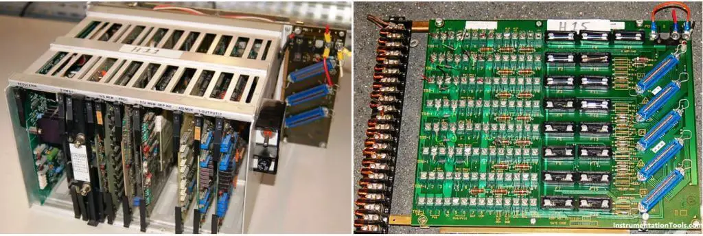
Each rack (called a “box” by Honeywell) consisted of an aluminum frame holding several large printed circuit boards with card-edge connectors. A “basic controller” box appears in the left-hand photograph.
The right-hand photograph shows the termination board where the field wiring (420 mA) connections were made. A thick cable connected each termination board to its respective controller box:
DCS Hardware
Controller redundancy in the TDC2000 DCS took the form of a “spare” controller box serving as a backup for up to eight other controller boxes. Thick cables routed all analog signals to this spare controller, so that it would have access to them in the event it needed to take over for a failed controller.
The spare controller would become active on the event of any fault in any of the other controllers, including failures in the I/O cards.
Thus, this redundancy system provided for processor failures as well as I/O failures. All TDC2000 controllers communicated digitally by means of a dual coaxial cable network known as the “Data Hiway.” The dual cables provided redundancy in network communications.
DCS Workstation
A typical TDC2000 operator workstation appears in the next photograph:
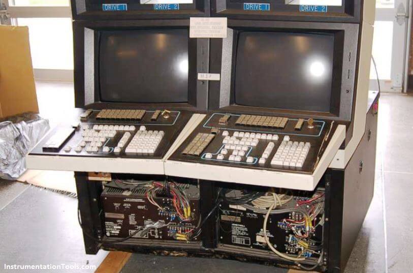
Over the years following its 1975 introduction, the Honeywell system grew in sophistication with faster networks (the “Local Control Network” or LCN), more capable controller racks (the “Process Manager” or PM series), and better operator workstations.
Many of these improvements were incremental, consisting of add-on components that could work with existing TDC2000 components so that the entire system need not be replaced to accept the new upgrades.
Other control equipment manufacturers responded to the DCS revolution started by Honeywell and Yokogawa by offering their own distributed control systems.
The Bailey Network 90 (Net90) DCS, Bailey Infi90 DCS, and the Fisher Provox systems are examples. Foxboro, already an established leader in the control system field with their SPEC 200 analog system, first augmented the SPEC 200 with digital capabilities (the VIDEOSPEC workstation consoles, FOX I/A computer, INTERSPEC and FOXNET data networks), then developed an entirely digital distributed control system, the SPECTRUM.
Some modern distributed control systems offered are :
- ABB 800xA
- Emerson DeltaV and Ovation
- Foxboro (Invensys) I/A
- Honeywell Experion PKS
- Yokogawa CENTUM VP and CENTUM CS
DCS IO Modules
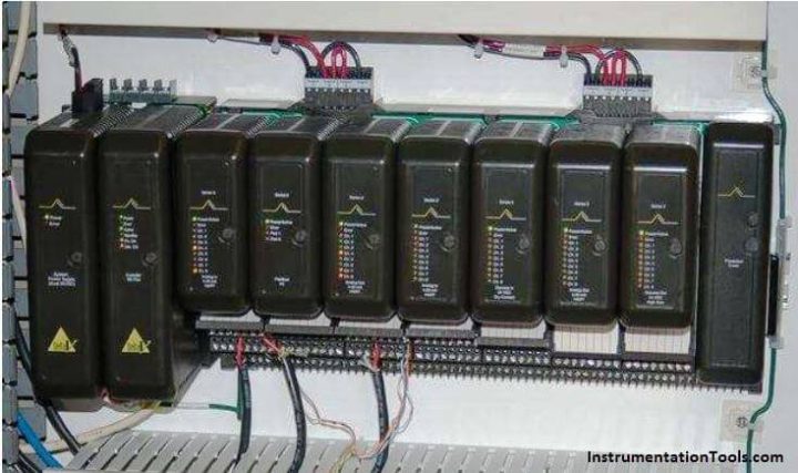
For a visual comparison with the Honeywell TDC2000 DCS, examine the following photograph of an Emerson DeltaV DCS rack, with processor and multiple I/O modules:
As previously mentioned in the Direct Digital Control (DDC) subsection, programmable logic controllers (PLCs) are becoming more and more popular as PID control platforms due to their ever-expanding speed, functionality, and relatively low cost.
It is now possible with modern PLC hardware and networking capabilities to build a truly distributed control system with individual PLCs as the processing nodes, and with redundancy built into each of those nodes so that any single failure does not interrupt critical control functions. Such a system may be purchased at a fraction of the up-front cost of a fully-fledged DCS.
However, what is currently lacking in the PLC world is the same level of hardware and software integration necessary to build a functional distributed control system that comes as ready-to-use as a system pre-built by a DCS manufacturer.
In other words, if an enterprise chooses to build their own distributed control system using programmable logic controllers, they must be prepared to do a lot of programming work in order to emulate the same level of functionality and power as a pre-engineered DCS.
Any engineer or technician who has experienced the power of a modern DCS – with its self-diagnostic, “smart” instrument management, event auditing, advanced control strategy, pre-engineered redundancy, data collection and analysis, and alarm management capabilities – realizes these features are neither luxuries nor are they trivial to engineer. Woe to anyone who thinks these critical features may be created by incumbent staff at a lesser cost!


good lessons