Inst ToolsInst ToolsInst Tools
  • Courses
  • Automation
    • PLC
    • Control System
    • Safety System
    • Communication
    • Fire & Gas System
  • Instrumentation
    • Design
    • Pressure
    • Temperature
    • Flow
    • Level
    • Vibration
    • Analyzer
    • Control Valve
    • Switch
    • Calibration
    • Erection & Commissioning
  • Interview
    • Instrumentation
    • Electrical
    • Electronics
    • Practical
  • Q&A
    • Instrumentation
    • Control System
    • Electrical
    • Electronics
    • Analog Electronics
    • Digital Electronics
    • Power Electronics
    • Microprocessor
Search
  • Books
  • Software
  • Projects
  • Process
  • Tools
  • Basics
  • Formula
  • Power Plant
  • Root Cause Analysis
  • Electrical Basics
  • Animation
  • Standards
  • 4-20 mA Course
  • Siemens PLC Course
Reading: Zero Elevation and Zero Suppression in Level Measurement
Share
Notification Show More
Font ResizerAa
Inst ToolsInst Tools
Font ResizerAa
  • Courses
  • Design
  • PLC
  • Interview
  • Control System
Search
  • Courses
  • Automation
    • PLC
    • Control System
    • Safety System
    • Communication
    • Fire & Gas System
  • Instrumentation
    • Design
    • Pressure
    • Temperature
    • Flow
    • Level
    • Vibration
    • Analyzer
    • Control Valve
    • Switch
    • Calibration
    • Erection & Commissioning
  • Interview
    • Instrumentation
    • Electrical
    • Electronics
    • Practical
  • Q&A
    • Instrumentation
    • Control System
    • Electrical
    • Electronics
    • Analog Electronics
    • Digital Electronics
    • Power Electronics
    • Microprocessor
Follow US
All rights reserved. Reproduction in whole or in part without written permission is prohibited.
Inst Tools > Blog > Level Measurement > Zero Elevation and Zero Suppression in Level Measurement

Zero Elevation and Zero Suppression in Level Measurement

Last updated: June 12, 2019 9:42 am
Editorial Staff
Level Measurement
4 Comments
Share
5 Min Read
SHARE

One of the most misunderstood concepts when dealing with transmitters is zero elevation and suppression. Elevation and suppression adjustments are frequently necessary in liquid level measurement when the transmitter cannot be installed on a level with the zero level of the tank.

Contents
Zero ElevationZero Suppression

The definition is following, but to understand elevation and suppression, its easiest if you look at it from a mathematical viewpoint, that is described in the second part of this paragraph.
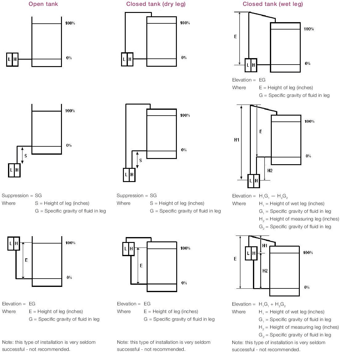
Zero Elevation

for an elevated zero range, the amount the measure variable zero is above the lower range value. It may be expressed either in units of measured variables or in percent of span.

Zero Suppression

for a suppressed zero range, the amount the measured variable zero is below the lower range value. It may be expressed either in units of the measured variable, or in percent of span.

Also Read: Zero Suppression & Zero Elevation Examples

Mathematically you can develop equations that will let you calibrate the transmitter for any given application requiring zero elevation or suppression. It’s important to understand some basic facts about differential pressure transmitters.

First, in order to obtain an increasing output, the high side of the transmitter must always be increasing in pressure relative to the low side.

Therefore, to achieve a 20 mA output, the net result of all forces on both the high and low sides of the transmitter must be such that the high side is greater than the low side by an amount equal to the calibrated span of the transmitter.

Second, the purpose of the calibration biases (elevation and suppression) is to apply a differential pressure to those situations where a     4 mA output is desired at some point other than 0 differential pressure.

Zero Elevation and Zero Suppression

Download the Zero Suppression & Zero Elevation Image

We know that for any situation, the sum total of effects on a transmitter should be zero for a 4 mA output.

Therefore at the desired 4 mA condition:

H – L+ B = O

Where:
H = is the pressure (relative to atmosphere) applied at the high side of the transmitter in inches H20

L = is the pressure (relative to atmosphere) applied at the low side of the transmitter in inches H20.

B = is the bias factor, in inches H20, which can be either positive or negative.

At a 20 mA condition:

H – L+ B = S

Where:
S = is the calibrated span of the transmitter, which can never be zero or negative.

So this gives us two equations:

H – L + B = O   at 4 mA
H – L + B = S    at 20 mA

With these two equations, it is now possible to determine the calibration for any situation according to the following procedures:

Analyse the specific application to identify all fluid forces on both sides of the transmitter at the point where you want 4 mA Output and the point where you want 20 mA output.

Using the 4 mA condition, solve for B in: H — L+ B = O

Using the 20 mA condition, and the value of B obtained from the above calculation, solve for S: H — L+ B = S

Calibrate the transmitter to a range of: (— B) to (— B + S)

For example, Figure below represents a closed tank application where we want a 4 mA output when the level is at the bottom tap and 20 mA output at the top tap.

Closed Tank Application

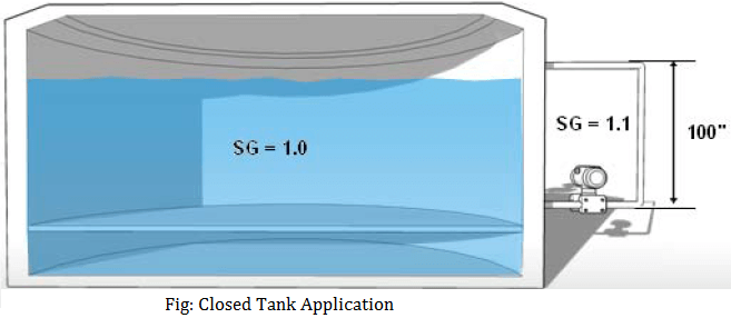
We also know that the low side leg is always filled with material whose specific gravity is 1.1. If the specific gravity of the fluid in the tank is 1.0, what is the calibration?

At 4 mA:

H = 0
L = 100” x 1.1 = 110” H20
So that:
H — L + B = 0
0 —110 + B = 0
B = 110

At 20 mA:

H = 100. x 1.0 = 100” H20
L= 100. x 1.1 = 110” H20
So that:
H — L + B = S
100 -110 + 110 = S
S = 100” H20

So our calibration for this application is: (— B) to (— B + S)
So: — 110 to (— 110 + 100)
calibration Range is: — 100 to -10” H20

Also Read: Pressure Transmitter Uses & Applications

Don't Miss Our Updates
Be the first to get exclusive content straight to your email.
We promise not to spam you. You can unsubscribe at any time.
Invalid email address
You've successfully subscribed !

Continue Reading

Stilling Wells for Level Measurement
Weight-based Level Measurement Principle
Inductively Coupled Wire Guided Float Detectors
Servo Tank Gauges Working Principle
Ultrasonic Tank Gauging
Closed Tank Level Measurement using DP Transmitters
Share This Article
Facebook Whatsapp Whatsapp LinkedIn Copy Link
Share
4 Comments
  • Surjith thomas says:
    February 8, 2017 at 2:13 pm

    Dear Sir,

    We have installed a level transmitter from E&H model PMD75 for measuring level of a tank (52 meter diameter) with height 14.5 meters.
    The transmitter is installed 1 meter above the zero level of the tank from the tapping which is 1.8 meter below tank zero level. (tapping is in the drain line of the tank below ground level)

    Actually we need to measure from the zero level of the tank.

    What shall be the LRV and URV to be put in the transmitter and in the PLC SCADA.

    Reply
    • S Bharadwaj Reddy says:
      February 8, 2017 at 5:31 pm

      Hi, Please CLICK HERE & follow the calculation formulas as mentioned.

      Reply
  • praveen kumar says:
    June 11, 2019 at 9:35 pm

    dear sir… i have one doubt..as you said that Zero elevation means measure variable is above the LRV
    Zero suppression means measure variable is below the LRV.

    for example:- My tank height is 1000mm and its an closed tank so i provided seal pot on LP side my seal pot inside liquid density is 1 and process liquid density also 1.. i just mount transmitter below the hp tapping approximately 500mm…

    so for Zero= HP(d) – LP(d)
    = 500(1)- 1500(1)
    = -1000mmwc

    for span= HP(d) – LP(d)
    = 1500(1) – 1500(1)
    = 0 mmwc

    so Range= -1000 to 0 mmwc

    example 2:- my tank height is 1000mm. i just place the transmitter above the hp tapping approximately 500mmwc. due to close tank i just put seal pot on lp side. from Lp tapping to transmitter also 500mm.

    so for Zero = HP(d) – LP(d)
    = 0(1) – 500(1)
    = -500 mmwc

    so for span = HP(d) – LP(d)
    = 1000(1) – 500 (1)
    = +500mmwc

    Range will be -500 to +500mmwc

    how can i say both of the installation is Zero suppression

    Reply
  • Malaya Pati says:
    December 18, 2022 at 5:36 pm

    Zero elevation and Zero suppression occurs in which type of level measurement and why?

    Reply

Leave a Reply Cancel reply

Your email address will not be published. Required fields are marked *

Stay Connected

128.3kFollowersLike
69.1kFollowersFollow
210kSubscribersSubscribe
38kFollowersFollow

Categories

Explore More

How to Install Ultrasonic Level Transmitters
Magnetic Level Indicators Working Animation
Capacitance Level Measurement Working Principle
Magnetostrictive Tank Gauging (MTG)
Interface Level Measurement Selection Guide
Radiation Level Measurement
DP Transmitter with Two Seals applications
Questions on Level Switches

Keep Learning

Paddle Wheel Level Switch Principle

Paddle Wheel Level Switch Principle

Differential Pressure Measurement

Basics of Differential Pressure Level Transmitters

Magnetic Level Indicator

Magnetic Level Indicator Principle, Limitations, Installation and Calibration

Closed tank DP Level Transmitter with wet leg elevation zero remote mount Calibration

Closed tank DP Level Transmitter with wet leg elevation zero remote mount Calibration

remote seal capillary type dp transmitter

Closed Tank Remote Seal Capillary type DP Transmitter

Float Level Switch Principle

Float Level Switch Working Principle Animation

Tuning Fork Level Switch principle

Tuning Fork Level Switch Principle

Bubble Tube Level measurement

Bubble Tube Level Measurement Principle

Learn More

Meters used in Troubleshooting Electrical Equipment

Meters used in Troubleshooting Electrical Equipment

Target Flow Transmitter Problem

Target Flow Transmitters Failed the Very Midnight

Analog signal with noise

Signal Coupling and Cable Separation

FMCW radar principle

TDR & FMCW Radar Level Transmitters Principle

Self-balancing Pneumatic Instrument Principles - 3

Self-balancing Pneumatic Instrument Principles

Electrical Networks Objective Questions

Electrical Networks Objective Questions

Quartzoid Bulb Detector Working Principle

Fire Water Sprinklers Working Principle

Control Valves Flow Direction

Control Valve Flow Direction

Menu

  • About
  • Privacy Policy
  • Copyright

Quick Links

  • Learn PLC
  • Helping Hand
  • Part Time Job

YouTube Subscribe

Follow US
All rights reserved. Reproduction in whole or in part without written permission is prohibited.
Welcome Back!

Sign in to your account

Username or Email Address
Password

Lost your password?