Inst ToolsInst ToolsInst Tools
  • Courses
  • Automation
    • PLC
    • Control System
    • Safety System
    • Communication
    • Fire & Gas System
  • Instrumentation
    • Design
    • Pressure
    • Temperature
    • Flow
    • Level
    • Vibration
    • Analyzer
    • Control Valve
    • Switch
    • Calibration
    • Erection & Commissioning
  • Interview
    • Instrumentation
    • Electrical
    • Electronics
    • Practical
  • Q&A
    • Instrumentation
    • Control System
    • Electrical
    • Electronics
    • Analog Electronics
    • Digital Electronics
    • Power Electronics
    • Microprocessor
Search
  • Books
  • Software
  • Projects
  • Process
  • Tools
  • Basics
  • Formula
  • Power Plant
  • Root Cause Analysis
  • Electrical Basics
  • Animation
  • Standards
  • 4-20 mA Course
  • Siemens PLC Course
Reading: What is Namur Digital Input Card?
Share
Notification Show More
Font ResizerAa
Inst ToolsInst Tools
Font ResizerAa
  • Courses
  • Design
  • PLC
  • Interview
  • Control System
Search
  • Courses
  • Automation
    • PLC
    • Control System
    • Safety System
    • Communication
    • Fire & Gas System
  • Instrumentation
    • Design
    • Pressure
    • Temperature
    • Flow
    • Level
    • Vibration
    • Analyzer
    • Control Valve
    • Switch
    • Calibration
    • Erection & Commissioning
  • Interview
    • Instrumentation
    • Electrical
    • Electronics
    • Practical
  • Q&A
    • Instrumentation
    • Control System
    • Electrical
    • Electronics
    • Analog Electronics
    • Digital Electronics
    • Power Electronics
    • Microprocessor
Follow US
All rights reserved. Reproduction in whole or in part without written permission is prohibited.
Inst Tools > Blog > PLC Tutorials > What is Namur Digital Input Card?

What is Namur Digital Input Card?

Last updated: March 4, 2021 12:15 pm
Editorial Staff
PLC Tutorials
No Comments
Share
2 Min Read
SHARE

What is Namur digital input card? And what it is used for? 

If you open the hardware configuration in the SIMATIC manager platform for Siemens PLC programming software and want to add a digital input card to your project you will notice some digital input modules with suffix NAMUR.

Namur Digital Input

NAMUR DI modules have the ability to receive NAMUR sensors signals and can detect if the sensor status is on, off, wire broken, or sensor short-circuited. But how the PLC can detect that?
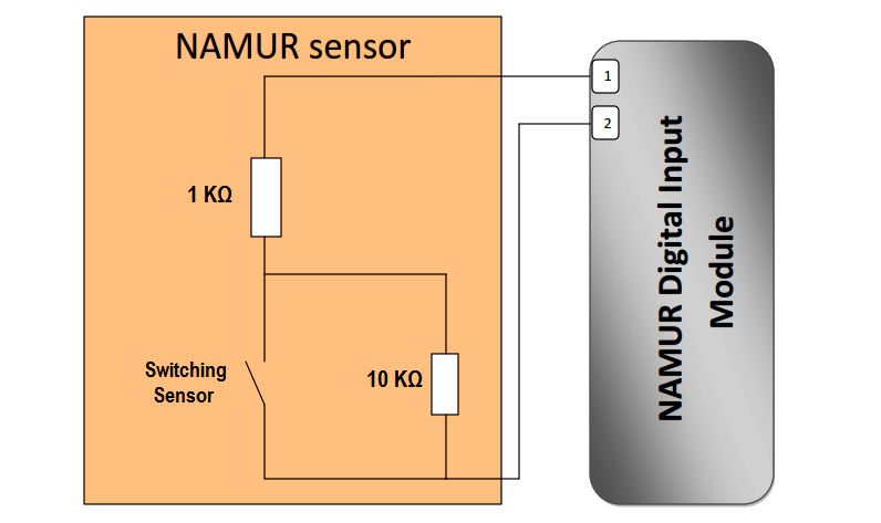
Namur Digital Input Card

From the above figure the NAMUR sensor circuit composed of sensing switch and resistances, the NAMUR DI module can detect the sensor resistance in the following cases.

In case of the sensor is off

The sensor’s total resistance = 10 KΩ+ 1 KΩ= 11KΩ

In case of the sensor is on

The sensor’s total resistance = 1 KΩ

Because in that case the 1 KΩ resistor is neglected by the ohms law

In case of wire broken

The sensor’s total resistance = ∞

In case of sensor short circuit

The sensor’s total resistance = 0

So the NAMUR sensor is a special digital sensor with a special modules to be connected to. But why we need all of this?

In some plants, there are sensors in critical positions where it’s important to know if the sensor is broken before it’s too late. Or in other plants, it’s used for personal safety protection and in minor cases to prevent electricians from bypassing the terminals of the sensor in order to simulate sensor on status.

Author: Karim Ali Anwar

If you liked this article, then please subscribe to our YouTube Channel for PLC and SCADA video tutorials.

You can also follow us on Facebook and Twitter to receive daily updates.

Read Next:

  • What is Namur NE 43?
  • What is Namur NE 107?
  • 2 wire Sensors Operation
  • 4-20 mA Namur Current Signals
  • Programmable Logic Controller
Don't Miss Our Updates
Be the first to get exclusive content straight to your email.
We promise not to spam you. You can unsubscribe at any time.
Invalid email address
You've successfully subscribed !

Continue Reading

Factory I/O PLC Automation Training Course (Free)
Tia Portal – OB121 Programming Errors Interrupt Organization Block
Understanding the Scan Cycle of SIEMENS PLC
PLC Program for Stage Control: Curtains and Stage Elevation
Up Down Counter Instruction in PLC
PLC Program for 2 Push buttons to Control 1 Output
Share This Article
Facebook Whatsapp Whatsapp LinkedIn Copy Link
Share
Leave a Comment

Leave a Reply Cancel reply

Your email address will not be published. Required fields are marked *

Stay Connected

128.3kFollowersLike
69.1kFollowersFollow
208kSubscribersSubscribe
38kFollowersFollow

Categories

Explore More

MCQ on PLC (Programmable Logic Controller)
Real-Time Clock in Omron PLC? – CX Programmer
How to Design a System Architecture in Industrial Automation?
What is PLC Redundancy?
Testing and Validation in PLC Development
Automation System for Hazardous Environments
Difference Between Static and Temp Memory in Siemens PLC TIA Portal
What are AI, AO, DI, and DO? – Definition, Examples, Purpose

Keep Learning

PLC Program Example on Multiple LEDs using Set Coil

PLC Program Example on Multiple LEDs using Set Coil

PLC Conveyor Forward and Reverse Logic

Advanced PLC Conveyor Control: Forward and Reverse Rotation

Pulse Timer Instruction in PLC Programming

Pulse Timer Instruction in PLC Programming

Siemens OB Blocks

Siemens PLC Organization Blocks (OB)

Mixing Tank Relay Circuit

PLC Program for Mixing Tank

Actuator Sensor Interface (ASi) Protocol in PLC

Actuator Sensor Interface (ASi) Protocol in PLC

Difference between Power Cables and Signal Cables

Difference between Power Cables and Signal Cables

Omron PLC Mixing System

Mixing Program with Timers and Counters in Omron PLC

Learn More

An Indian Plants all turbines’ low Vacuum

An Indian Plants all turbines’ low Vacuum & Saudi Plant turbo-compressor only

Power Electronics objective questions and answers

Top 50 Power Electronics Quiz

Pressure Transmitter

Pressure Transmitter Animation

Hair Hydrometer Principle

Hair Hydrometer Principle

Emergency ShutDown Valve Working Principle

ESDV : How it Works ?

How to Install Thermowell on an Elbow?

Power Systems Questions & Answers

Power Systems MCQ Series 2

A Large Gate Valve Failed Motorized Operation

A Large Gate Valve’s Failed Motorized Operation

Follow US
All rights reserved. Reproduction in whole or in part without written permission is prohibited.
Welcome Back!

Sign in to your account

Username or Email Address
Password

Lost your password?