Inst ToolsInst ToolsInst Tools
  • Courses
  • Automation
    • PLC
    • Control System
    • Safety System
    • Communication
    • Fire & Gas System
  • Instrumentation
    • Design
    • Pressure
    • Temperature
    • Flow
    • Level
    • Vibration
    • Analyzer
    • Control Valve
    • Switch
    • Calibration
    • Erection & Commissioning
  • Interview
    • Instrumentation
    • Electrical
    • Electronics
    • Practical
  • Q&A
    • Instrumentation
    • Control System
    • Electrical
    • Electronics
    • Analog Electronics
    • Digital Electronics
    • Power Electronics
    • Microprocessor
  • Request
Search
  • Books
  • Software
  • Projects
  • Process
  • Tools
  • Basics
  • Formula
  • Power Plant
  • Root Cause Analysis
  • Electrical Basics
  • Animation
  • Standards
  • 4-20 mA Course
  • Siemens PLC Course
Reading: TDR & FMCW Radar Level Transmitters Principle
Share
Notification Show More
Font ResizerAa
Inst ToolsInst Tools
Font ResizerAa
  • Courses
  • Design
  • PLC
  • Interview
  • Control System
Search
  • Courses
  • Automation
    • PLC
    • Control System
    • Safety System
    • Communication
    • Fire & Gas System
  • Instrumentation
    • Design
    • Pressure
    • Temperature
    • Flow
    • Level
    • Vibration
    • Analyzer
    • Control Valve
    • Switch
    • Calibration
    • Erection & Commissioning
  • Interview
    • Instrumentation
    • Electrical
    • Electronics
    • Practical
  • Q&A
    • Instrumentation
    • Control System
    • Electrical
    • Electronics
    • Analog Electronics
    • Digital Electronics
    • Power Electronics
    • Microprocessor
  • Request
Follow US
All rights reserved. Reproduction in whole or in part without written permission is prohibited.
Inst Tools > Blog > Level Measurement > TDR & FMCW Radar Level Transmitters Principle

TDR & FMCW Radar Level Transmitters Principle

Last updated: March 12, 2019 10:31 am
Editorial Staff
Level Measurement
No Comments
Share
4 Min Read
SHARE

TDR & FMCW Radar Level Transmitters Principle

Continuous level measurement via radar is based on the theory of the propagation of electromagnetic waves, put forth by the British physicist James C. Maxwell in 1865. Maxwell postulated that the field lines of a changing magnetic field are surrounded by annular electrical field lines, even in the absence of electrical conductors.

Inspired by this theory, German physicist Christian Hülsmeyer immediately applied for a patent for his telemobiloscope, the first radar device of this type in Düsseldorf in 1904. For this innovation, he is rightly known as the the inventor of the „original radar.“

Frequency Modulated Continuous Wave (FMCW) :

A radar signal is emitted via an antenna, reflected on the product surface and received after a time t. The radar principle used is FMCW (Frequency Modulated Continuous Wave). The FMCW radar emits a high frequency signal whose frequency increases linearly during the measurement phase (called the frequency sweep). The signal is emitted, reflected from the measuring surface and received with a time delay, t. Delay time, t=2d/c, where d is the distance to the product surface and c is the speed of light in the gas above the product. For further signal processing the difference Δf is calculated from the actual transmit frequency and the receive frequency. The difference is directly proportional to the distance.

FMCW radar principle

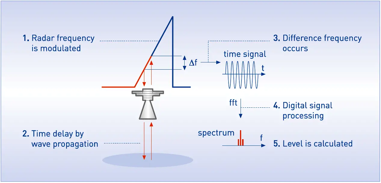
A large frequency difference corresponds to a large distance and vice versa. The frequency difference Δf is transformed via a Fourier transformation (FFT) into a frequency spectrum and then the distance is calculated from the spectrum. The level results from the difference between tank height and measuring distance.

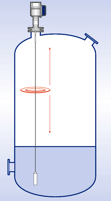
TDR: Time Domain Reflectometry

The device transmits low-intensity electromagnetic pulses of approximately one nanosecond width along a rigid or flexible conductor. These pulses move at the speed of light. When the pulses reach the surface of the product to be measured, the pulses are reflected with an intensity that depends on the dielectric constant, εr, of the product (for example, water has a high dielectric constant and reflects the pulse back to the meter converter at 80 % of its original intensity).

The device measures the time from when the pulse is transmitted to when it is received: half of this time is equivalent to the distance from the reference point of the device (the flange facing) to the surface of the product. The time value is converted into an output current of 4 to 20 mA and/or a digital signal.

TDR Radar Principle

Dust, foam, vapor, agitated surfaces, boiling surfaces, changes in pressure, temperature and density do not have an effect on device performance.
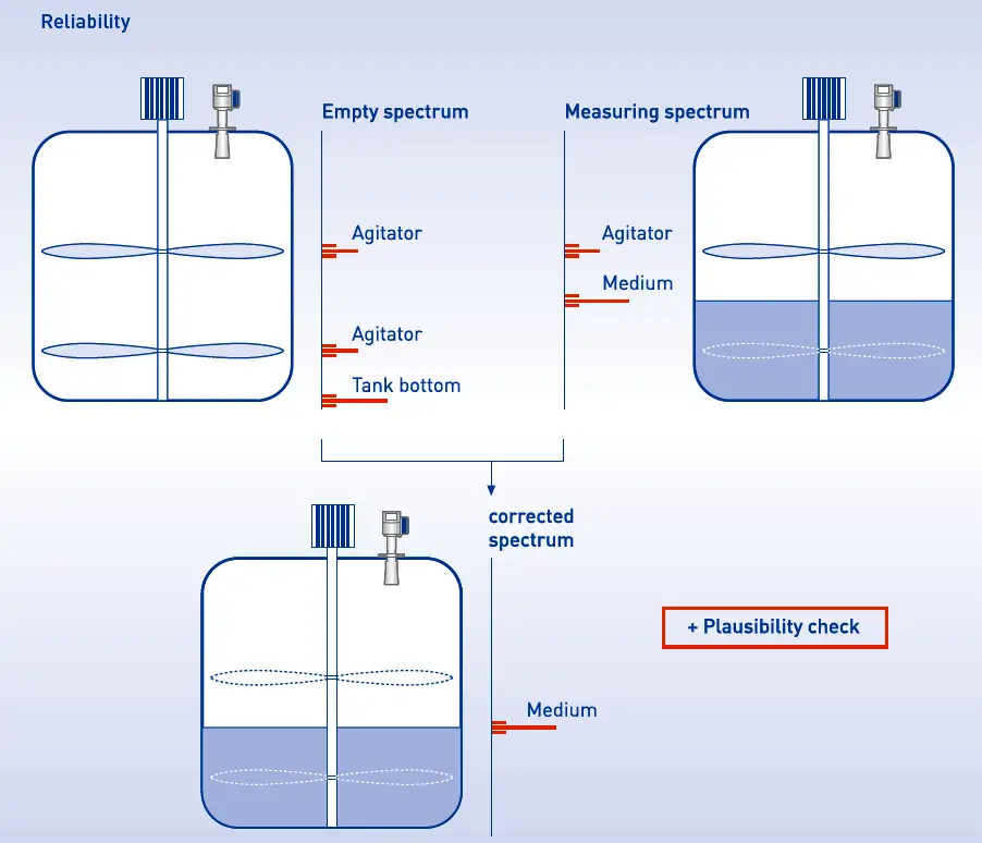
Empty spectrum

All interference reflections, which are caused by fixed or moving tank inserts and the bottom of the tank, can be detected and saved by recording an empty spectrum. The surface reflections are reliably detected, distinguished from interference reflections and analyzed by comparing the empty spectrum to the reflections in the filled state. For applications with tanks that cannot be emptied at the time of the start-up, the radar meters offer the capability of recording a partially empty spectrum.

RADAR Level echo

Source : Khrone

Image Credits : Khrone

Don't Miss Our Updates
Be the first to get exclusive content straight to your email.
We promise not to spam you. You can unsubscribe at any time.
Invalid email address
You've successfully subscribed !

Continue Reading

How can we use a DP Flow Transmitter for Level Measurement
Basics of DP Level Measurement
What are Mechanical Level Indicators? – Classification & Principle
Capacitive Tank Gauges
Displacer Level Transmitter Calibration using Water & Process Liquid
Closed tank DP Level Transmitter with wet leg elevation zero direct mount Calibration
Share This Article
Facebook Whatsapp Whatsapp LinkedIn Copy Link
Share
Leave a Comment

Leave a Reply Cancel reply

Your email address will not be published. Required fields are marked *

Stay Connected

128.3kFollowersLike
69.1kFollowersFollow
210kSubscribersSubscribe
38kFollowersFollow

Categories

Explore More

Closed Tank Level Measurement using DP Transmitters
Manual Level Measurement
Difference between Transparent Level Gauge and Reflex Level Gauge
Potentiometric Level Measurement Principle
Level Instruments General Specifications
Calibration of Displacer Level Transmitter
Level Gauge Interface & Temperature Problems
Tuning Fork Level Switch Principle

Keep Learning

Sounding Level Transmitter Working Animation

level gauge

Basics of Sight Glass Level Gauge

Closed Tank Application

Zero Elevation and Zero Suppression in Level Measurement

Tilt Level Switch Theory

Tilt Level Switch Working Principle

Tilt Level Switch Working Animation

Submersible Pressure Transmitter

What is a Submersible Pressure Transmitter? Principle, Advantages

Float Level Switch Principle

Float Level Switch Working Principle Animation

Level Gauge Working Animation

Sight Glass Level Measurement Principle

Learn More

Difference between Current Transformer and Potential Transformer

Difference between Current Transformer and Potential Transformer

Relay Types

Types of Relays – Questions and Answers

5 Tips to Pass CFSE Exam

5 Tips to Pass CFSE Exam

surface-mounted water pump

Surface-mounted Water Pump

Evolution of Air Compressors

The Evolution of Air Compressors: From Power to Silence

Purpose of Stop in a Pressure Measuring Instrument

Purpose of Stop in a Pressure Measuring Instrument

Ammonia Analyzer Working

Ammonia Analyzer Principle

Purpose of Emergency Shutdown (ESD) System

Purpose of Emergency Shutdown (ESD) System

Menu

  • About
  • Privacy Policy
  • Copyright

Quick Links

  • Learn PLC
  • Helping Hand
  • Part Time Job

YouTube Subscribe

Follow US
All rights reserved. Reproduction in whole or in part without written permission is prohibited.
Welcome Back!

Sign in to your account

Username or Email Address
Password

Lost your password?