Interposing Relay is the auxiliary relay which is used to isolate the two different systems / devices. This could be because they have different 0V references, different voltages, AC vs. DC.
Interposing Relay
We discuss the interposing relay with two cases, as discussed below :
Case-I
Suppose we want to operate a Contactor through PLC Panel having Coil Voltage 230 V AC, But PLC relay Output Voltage is 24 V DC. In this case we require a Interposing relay Having Coil Voltage 24 V DC but its contact rating should be 230 V AC.
So PLC relay will operate interposing relay first & then through its Auxiliary contacts We can Operate Contactor easily.
Case-II
For example, let’s say the relay of a PLC can only avail 1 A at 110 VAC, but the Controller which is to be connected to the relay requires 3 A at 110 VAC.
In this case, an interposing relay with contacts rated for operation at 5 A(>3 A) at 110 VAC would be used as an interposing relay “between” the PLC relay and the Controller.
The coil of the interposing relay should require less voltage and current than the driving relay is rated for, and the contacts of the interposing relay must be rated to handle the requirements of the load ( Controller).
Example :
In addition to directly performing logic functions, electromechanical relays may also be used as interposing devices between mismatched sensors, controllers, and/or control devices.
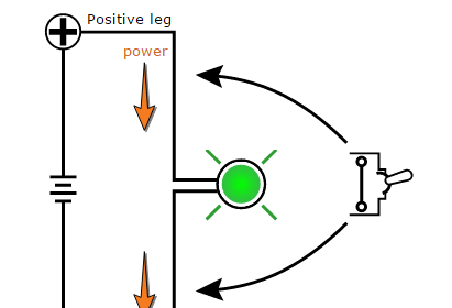
A very simple example of a relay used to interpose between mismatched devices is shown in the following circuit diagram, where a delicate toggle switch is used to control a bank of high-power lights for an off-road vehicle:

In this circuit the relay performs no logic function whatsoever. Rather, it merely “amplifies” the signal sent by the dashboard toggle switch to send or halt power to the bank of high-power lights.
Without the relay, a much heavier-duty toggle switch would have to be installed in the dashboard of this vehicle to safely and reliably make and break the light circuit.
Also Read : Mis-conceptions of PLC Ladder Logic
Another example of an interposing relay found in automotive applications is the use of a “solenoid” in the electric starting motor circuit for an internal combustion engine.
The “start” control switch is typically actuated by the driver turning a key, that switch mounted on the steering column or dashboard of the vehicle. The starting motor, meanwhile, typically draws hundreds of amps of current as it labors to start up the engine.
A key switch capable of making and breaking hundreds of amps of current would be enormous, and in fact dangerous to locate in the cab of the vehicle.
The “solenoid” relay connected between the key-switch and the starting motor relocates that danger, and allows a relatively delicate keyswitch to safely activate the high-power motor.
An industrial example of an interposing relay between mismatched devices is shown here, where a DC output proximity switch must trigger an input channel to a Programmable Logic Controller (PLC) rated for 120 volts AC:

Again, the relay in this system performs no logic function, but merely allows the proximity switch to drive one of the PLC input channels.
Directly connecting the proximity switch to one of the input channels of the PLC is not a practical option, because this particular PLC input requires 120 volts AC to activate, and our proximity switch operates on 24 volts DC.
The mismatch between switch voltage and PLC input voltage requires us to use the relay to “interpose” between the switch and PLC.
When the proximity switch senses an object nearby, its output activates, which in turn energizes the relay coil. When the relay contact magnetically closes, it completes a circuit for 120 volts AC to reach input channel 0 on the PLC, thereby energizing it.
An important detail in this relay circuit is the inclusion of a commutating diode in parallel with the relay coil, the purpose being to dissipate the coil’s stored energy upon de-energization when the proximity switch turns off.
Without this diode in place, the coil’s “kickback” voltage (which may reach hundreds of volts in potential) will destroy the proximity switch’s output transistor.
Note how this commutating diode appears to be connected “backwards” with regard to the polarity of the 24 volt DC power source: cathode toward the source’s positive pole and anode toward the source’s negative pole.
This is intentional, as we do not wish to have the diode conduct when power is applied to the relay coil through the proximity switch (If the diode were connected the other way, it would pass current whenever the proximity switch turned on, shorting past the relay coil and most likely damaging the proximity switch in doing so!).
The diode only turns on when the polarity reverses, which is what happens when the proximity switch turns off and the relay coil’s magnetic field collapses (now acting as a source rather than as a load).
As the relay coil temporarily outputs a “reverse” voltage, the diode gives that coil a continuous path for its current while dropping a low voltage (about 0.7 volts DC), dissipating the coil’s stored energy in the form of heat at the diode.
Also Read : PLC Analog Input Scaling
Interposing relays are also used to connected mismatched PLC outputs and control devices. In this application, the mismatch may be in terms of voltage ratings and/or current ratings.
As with the input interposing circuit shown previously, the task of the relay in an output interposing circuit is to be controlled by the PLC’s output channel, and in turn direct power to a field device that is itself incompatible with the PLC’s output.
The following diagram shows an example of an interposing relay connected to a PLC output channel:

In this circuit the PLC’s transistor outputs can only handle 24 volts DC, and at fairly low current. The three-phase contactor coil requires 120 volts AC at modest current levels to function, and so the relay interposes between the PLC’s low-voltage and low-current output channel and the relatively high-voltage and high-current demands of the contactor’s coil.
Once again we see the use of a commutating diode to dissipate the relay coil’s stored energy whenever the PLC de-energizes it, so that the resulting “kickback” voltage does not damage the fragile transistor output circuitry within the PLC.
Credits : by Tony R. Kuphaldt – Creative Commons Attribution 4.0 License
If you liked this article, then please subscribe to our YouTube Channel for PLC and SCADA video tutorials.
You can also follow us on Facebook and Twitter to receive daily updates.
Read Next:


Instrumentationtools.com is really a very good source of information. As professionals, it equips us with knowdege.