In industrial automation, 24 VDC power is the backbone of every PLC system. Engineers often assume that if a power supply is rated correctly and a multimeter shows 24V, the system is electrically healthy. In reality, many PLC faults occur even when the 24 VDC supply appears normal.
24 VDC Systems
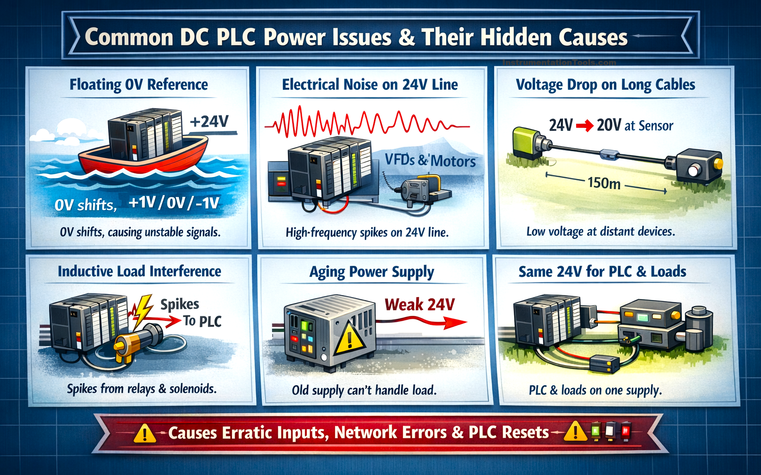
These faults are not caused by complete power loss, but by hidden issues like voltage dips, noise, poor grounding, or dynamic load behavior. Understanding how a healthy-looking 24 VDC system can still disturb PLC operation is critical for reliable control system design and effective plant troubleshooting, which we will see in this post.
Voltage collapses during load switching
The first issue occurs when the 24 VDC supply is stable in normal conditions, but cannot handle sudden load changes. In a plant, devices such as solenoid valves, relay coils, and contactors require a higher current at the instant they switch ON, called inrush current. If the power supply is slightly undersized, or the cable length and terminals introduce resistance, the voltage at the PLC terminals momentarily drops for a few milliseconds.
This drop is extremely fast, so a multimeter still shows around 24V, and the engineer assumes the supply is fine. However, the PLC CPU continuously monitors its operating voltage, and if it falls below its minimum threshold (typically near 19–20V), the PLC internally experiences a brownout.
The processor may restart, communication modules may disconnect, and remote I/O stations may go offline. Because the voltage recovers immediately, the system starts again, creating confusing intermittent faults that look like network or program issues, while the actual cause is a brief power dip during load switching.
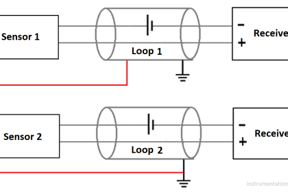
Floating 0 V
Another important cause is a floating 0V reference, which is often misunderstood in control panels. In a 24 VDC system, +24V is always measured relative to 0V (DC common). This 0V is the reference level for all PLC inputs, just like ground level is the reference for measuring height. If the 0V is not bonded to the panel earth (PE) at one proper point, it does not stay fixed. Due to electrical noise from VFDs, motors, and nearby power cables, the 0V line itself starts shifting slightly in voltage.
“Moving” here literally means the 0V is no longer exactly 0 volts. It may become +0.5V, +1V, +2V, or sometimes even 1V for a moment. A multimeter still shows about 24V because it measures between +24V and that same shifted 0V, so the supply appears healthy. But the PLC internally compares input signals with its own stable reference.
So if a sensor sends 24V and the 0V has shifted to +2V, the PLC effectively sees only 22V. If it shifts more, the signal may drop below the input detection threshold, making the PLC think the sensor turned OFF. This is why a sensor LED can be ON while the PLC input flickers or communication errors appear. Properly bonding the 0V to earth at one location stabilizes the reference and stops these confusing faults.
Noise on the 24 VDC line
The next issue is electrical noise riding on the 24V DC line. In theory, a DC supply should be smooth and constant, but inside a factory, it rarely stays pure. Equipment such as VFDs, servo drives, welding machines, and SCR heaters switches high currents at high frequency. These create electromagnetic interference that couples into nearby control cables. As a result, the 24V line is no longer only DC, but small high-frequency spikes and ripples get superimposed on it.
A multimeter averages the value, so it still shows a steady 24.0V, and the supply appears perfectly fine. However, PLC electronics and communication modules react to very fast changes in voltage. Those tiny spikes momentarily disturb the internal logic levels of input cards and communication circuits.
The PLC may then misread pulses, analog values may fluctuate even when the process is stable, encoders may give wrong counts, and networks like Ethernet/IP, Profinet, or Profibus may show random communication errors. The problem is not a lack of voltage but poor voltage quality, because the PLC is receiving 24V, but it is a noisy 24V, which leads to intermittent and very confusing faults.
Voltage drop along long field cables
Another common problem is voltage drop along long field cables. The 24V power supply inside the panel may be perfectly healthy, but the voltage that actually reaches the field device becomes lower because every wire has resistance. When sensors or transmitters are installed far from the panel, sometimes 50 to 150 meters away, part of the voltage is lost along the cable, especially if the conductor size is small or several devices share the same supply line.
In this situation, the sensor does operate, but it cannot deliver a strong output signal back to the PLC. PLC digital input cards require a minimum voltage (typically around 15-18V) to reliably recognize a logic ON. Due to the cable loss, the return signal reaching the PLC input hovers close to this limit, so the PLC interprets it inconsistently. The machine may stop intermittently, inputs appear unstable in diagnostics, and the problem seems like a faulty PLC channel, while the real cause is insufficient voltage available at the field device because of cable distance and resistance.
Aging or degraded 24 VDC power supply
The next hidden issue is an aging or degraded 24V power supply. Over time, especially in hot control panels, the internal components of an SMPS, particularly electrolytic capacitors, begin to deteriorate. This does not cause an immediate failure. The supply still turns ON, the LED is green, and a multimeter shows a steady 24V at no load or light load. So electrically, it appears completely healthy.
The real problem appears under dynamic conditions. When the machine starts, multiple outputs energize, or communication modules become active, the supply must respond quickly to changing current demand. A healthy SMPS adjusts instantly and keeps the voltage stable. An aging one reacts slowly, produces higher ripple, and struggles to maintain regulation. The voltage may momentarily sag or fluctuate internally, even if the average reading remains near 24V.
This leads to very confusing symptoms: PLC restarts during startup, random communication dropouts, analog signal instability, or unexplained safety trips. Engineers often suspect software bugs, firmware issues, or network faults. After hours or days of troubleshooting, simply replacing the old 24V supply resolves everything. The supply never fully failed; it just lost its ability to maintain stable power under real operating conditions.
Shared 24 VDC power supply
Another major cause is sharing the same 24V supply for PLC electronics and inductive loads. In many panels, one single SMPS is used to power the PLC CPU, I/O cards, communication modules, solenoid valves, relay coils, and contactors. Electrically, this works, but practically, it creates instability. Inductive devices like solenoids and relays generate voltage spikes when they switch OFF.
This happens because the collapsing magnetic field inside the coil produces a reverse voltage (back EMF). Even if flyback diodes or suppression circuits are installed, small transients still travel back into the 24V line. Since the PLC and its sensitive electronics are connected to the same supply, these spikes directly reach the CPU and communication modules.
The average voltage may still be 24V, and a multimeter shows nothing abnormal. However, these fast transients can cause the PLC to reset, communication modules to disconnect, analog cards to show channel errors, or safety PLCs to trip unexpectedly. The issue is not insufficient voltage, but disturbance injected into the control electronics because high-power inductive loads share the same 24V source. Proper design practice is to separate PLC/control power from field actuator power to avoid such hidden faults.