Inst ToolsInst ToolsInst Tools
  • Courses
  • Automation
    • PLC
    • Control System
    • Safety System
    • Communication
    • Fire & Gas System
  • Instrumentation
    • Design
    • Pressure
    • Temperature
    • Flow
    • Level
    • Vibration
    • Analyzer
    • Control Valve
    • Switch
    • Calibration
    • Erection & Commissioning
  • Interview
    • Instrumentation
    • Electrical
    • Electronics
    • Practical
  • Q&A
    • Instrumentation
    • Control System
    • Electrical
    • Electronics
    • Analog Electronics
    • Digital Electronics
    • Power Electronics
    • Microprocessor
  • Request
Search
  • Books
  • Software
  • Projects
  • Process
  • Tools
  • Basics
  • Formula
  • Power Plant
  • Root Cause Analysis
  • Electrical Basics
  • Animation
  • Standards
  • 4-20 mA Course
  • Siemens PLC Course
Reading: How to Install Ultrasonic Level Transmitters
Share
Font ResizerAa
Inst ToolsInst Tools
Font ResizerAa
  • Courses
  • Design
  • PLC
  • Interview
  • Control System
Search
  • Courses
  • Automation
    • PLC
    • Control System
    • Safety System
    • Communication
    • Fire & Gas System
  • Instrumentation
    • Design
    • Pressure
    • Temperature
    • Flow
    • Level
    • Vibration
    • Analyzer
    • Control Valve
    • Switch
    • Calibration
    • Erection & Commissioning
  • Interview
    • Instrumentation
    • Electrical
    • Electronics
    • Practical
  • Q&A
    • Instrumentation
    • Control System
    • Electrical
    • Electronics
    • Analog Electronics
    • Digital Electronics
    • Power Electronics
    • Microprocessor
  • Request
Follow US
All rights reserved. Reproduction in whole or in part without written permission is prohibited.
Inst Tools > Blog > Erection & Commissioning > How to Install Ultrasonic Level Transmitters

How to Install Ultrasonic Level Transmitters

Last updated: August 31, 2019 2:27 pm
Editorial Staff
Erection & Commissioning Level Measurement
No Comments
Share
1 Min Read
SHARE

Keep Ultrasonic Level Transmitter perpendicular to liquid.

How to Install Ultrasonic Level Transmitters 1

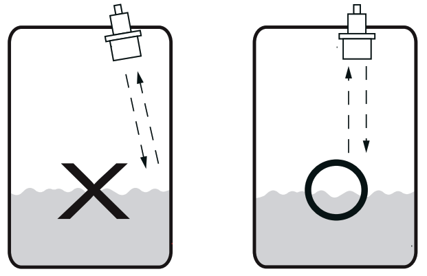
The transducer should not be mounted too close to the tank wall, the bracket can cause strong false echoes.

How to Install Ultrasonic Level Transmitters 2

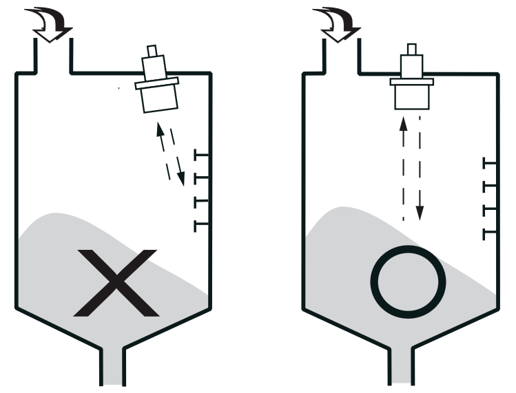
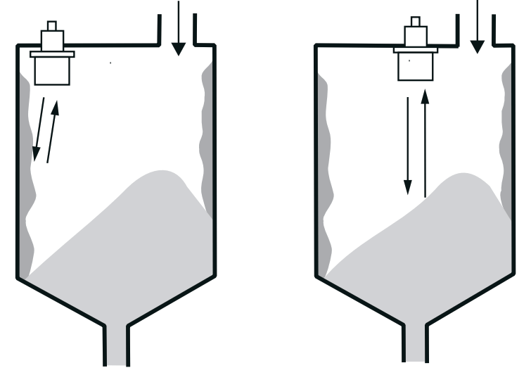
Mount the transducer away from the inlet to avoid false echoes.

How to Install Ultrasonic Level Transmitters 3

The transducer should not be mounted too close to the tank wall, the build-up on the tank wall cause false echoes.

How to Install Ultrasonic Level Transmitters 4

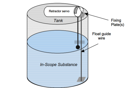
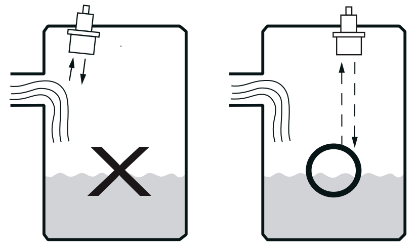
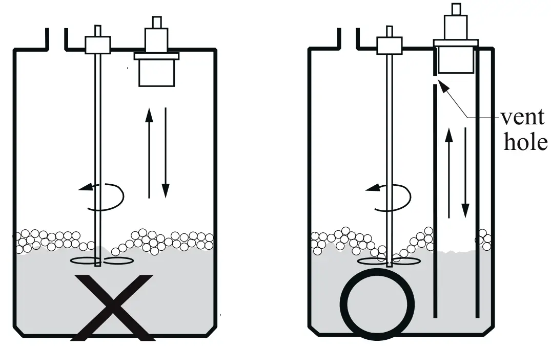
As is illustrated by the figure on the right, the transducer should be mounted on the top of guide tube to prevent the false echoes from turbulence and foam. The guide tube should come with a vent hole at top of the tube to allow the liquid vapor go out of the tube.

How to Install Ultrasonic Level Transmitters 5

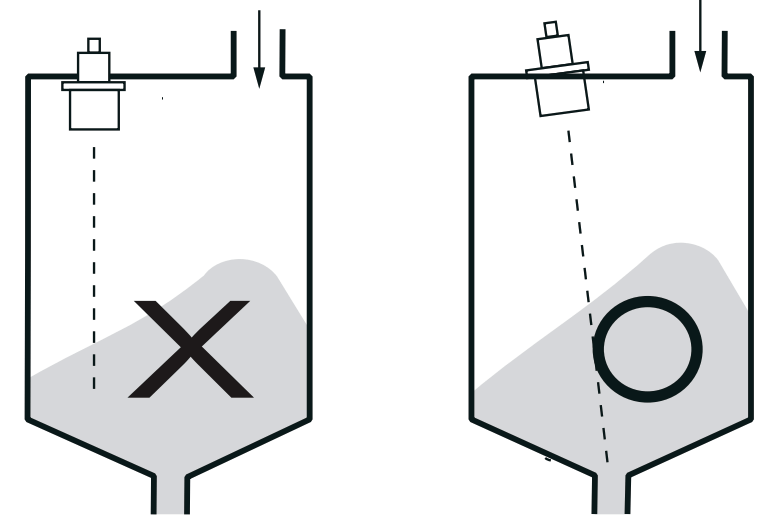
When you mount the transducer on the solid tank, the transducer must point to the tank outlet.

How to Install Ultrasonic Level Transmitters 6

Article Source : FineTek

Don't Miss Our Updates
Be the first to get exclusive content straight to your email.
We promise not to spam you. You can unsubscribe at any time.
Invalid email address
You've successfully subscribed !

Continue Reading

DP Level Transmitter Elevation and Suppression Corrections
Installation & Commissioning Tips for HART Devices
What is Double Block and Bleed Valves?
Instrument Tube Fitting Installation – Part 1
DP Transmitter with Two Seals applications
Magnetic Float Level Transmitter Working Principle
Share This Article
Facebook Whatsapp Whatsapp LinkedIn Copy Link
Share
Leave a Comment

Leave a Reply Cancel reply

Your email address will not be published. Required fields are marked *

Stay Connected

128.3kFollowersLike
69.1kFollowersFollow
210kSubscribersSubscribe
38kFollowersFollow

Categories

Explore More

Why Measure Level
Closed tank DP Level Transmitter with cleaning leg Calibration
Boiler Three Element Controller Philosophy
Magnetostrictive Tank Gauging (MTG)
How can we use a DP Flow Transmitter for Level Measurement
Difference between Transparent Level Gauge and Reflex Level Gauge
P&ID Guidelines for Pumps
Pressure Transmitter Heated Enclosures

Keep Learning

Closed-Tank-DP-Type-Level-Measurement-with-Dry-leg-and-transmitter-installed-below-tapping-point

Level Measurement with Dry leg and Installed Below Tapping Point

Magnetic Level Indicator

Magnetic Level Indicator Principle, Limitations, Installation and Calibration

Reflex Level Gauge Parts

What is Reflex Level Gauge?

Which instrument is at fault in this system

Which Instrument is at Fault in this System?

Pressure Transmitters Installation Factors

Pressure Transmitters Installation Tips

Open-Tank-DP-Level-Transmitter-with-Zero-Suppression-Calibration

DP Level Transmitter with Zero Suppression Calibration

RF-Capacitance Level Switch Principle

RF Capacitance Level Switch Working Principle

level-transmitter-calibration-procedure

Level Transmitter Calibration Procedure

Learn More

Gas Turbine Temperature Control using Siemens Tia Portal

Gas Turbine Temperature Alarms using Siemens TIA Portal

Bracelet Scanner

How to Use Bracelet Scanner? – Ultrasonic Thickness Gauge

Advantages of Three Phase System Compared to Single Phase System

Advantages of Three Phase System Compared to Single Phase System

Heat Exchanger Differential Pressure Transmitter

Heat Exchanger Differential Pressure Transmitter

Short Notes on Rectifiers & Filters

Short Notes on Rectifiers & Filters

DC Motor Action

DC Motor Speed

Troubleshooting Pump Control Circuit

Troubleshooting Pump Control Circuit

Allen-Bradley MicroLogix PLC Wiring

Programmable Logic Controller (PLC) Questions and Answers – 8

Menu

  • About
  • Privacy Policy
  • Copyright

Quick Links

  • Learn PLC
  • Helping Hand
  • Part Time Job

YouTube Subscribe

Follow US
All rights reserved. Reproduction in whole or in part without written permission is prohibited.
Welcome Back!

Sign in to your account

Username or Email Address
Password

Lost your password?