Inst ToolsInst ToolsInst Tools
  • Courses
  • Automation
    • PLC
    • Control System
    • Safety System
    • Communication
    • Fire & Gas System
  • Instrumentation
    • Design
    • Pressure
    • Temperature
    • Flow
    • Level
    • Vibration
    • Analyzer
    • Control Valve
    • Switch
    • Calibration
    • Erection & Commissioning
  • Interview
    • Instrumentation
    • Electrical
    • Electronics
    • Practical
  • Q&A
    • Instrumentation
    • Control System
    • Electrical
    • Electronics
    • Analog Electronics
    • Digital Electronics
    • Power Electronics
    • Microprocessor
Search
  • Books
  • Software
  • Projects
  • Process
  • Tools
  • Basics
  • Formula
  • Power Plant
  • Root Cause Analysis
  • Electrical Basics
  • Animation
  • Standards
  • 4-20 mA Course
  • Siemens PLC Course
Reading: Standard 4 to 20 mA Conversion Formula
Share
Notification Show More
Font ResizerAa
Inst ToolsInst Tools
Font ResizerAa
  • Courses
  • Design
  • PLC
  • Interview
  • Control System
Search
  • Courses
  • Automation
    • PLC
    • Control System
    • Safety System
    • Communication
    • Fire & Gas System
  • Instrumentation
    • Design
    • Pressure
    • Temperature
    • Flow
    • Level
    • Vibration
    • Analyzer
    • Control Valve
    • Switch
    • Calibration
    • Erection & Commissioning
  • Interview
    • Instrumentation
    • Electrical
    • Electronics
    • Practical
  • Q&A
    • Instrumentation
    • Control System
    • Electrical
    • Electronics
    • Analog Electronics
    • Digital Electronics
    • Power Electronics
    • Microprocessor
Follow US
All rights reserved. Reproduction in whole or in part without written permission is prohibited.
Inst Tools > Blog > Formulas > Standard 4 to 20 mA Conversion Formula

Standard 4 to 20 mA Conversion Formula

Last updated: February 28, 2020 5:10 pm
Editorial Staff
Formulas
16 Comments
Share
2 Min Read
SHARE

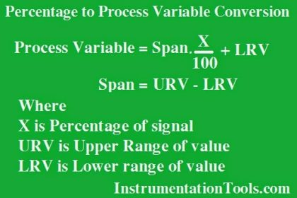
A 4 to 20 mA current signal represents a 0 to 100 percent scale. Usually, this scale is linear, as such:

Contents
4 to 20 mA Conversiony = mx + b

4 to 20 mA Conversion

4 to 20 mA current signal represents

Being a linear function,  we may use the standard slope-intercept linear equation to relate signal percentage to current values:

y = mx + b

Where,
y = Output from instrument
x = Input  to instrument
m = Slope
b = y-intercept point (i.e.  the live zero of the instrument’s range)

Once we determine suitable values for m and b, we may then use this linear equation to predict any value for y given x, and vice-versa.  This is very useful for predicting the 4-20 mA signal output of a process transmitter, or the expected  stem position of a 4-20 mA controlled valve, or any other correspondence  between  a 4-20 mA signal and some physical  variable.

Before we may use this equation for any practical purpose, we must determine the slope (m) and intercept (b) values appropriate for the instrument we wish to apply  the equation to. Next, we will see some examples  of how to do this.

For the linear function  shown, we may determine the slope value (m)  by dividing  the line’s rise by  its run.   Two  sets  of convenient points we may  use in calculating rise over  run  are  4 and  20 milliamps  (for the rise), and 0 and 100 percent (for the run):

4 to 20 mA Signal Plot

Easy 4 to 20 mA Formula

4 to 20 mA Calculation Example

Also Read: Basics of 4-20mA Current Signal

Don't Miss Our Updates
Be the first to get exclusive content straight to your email.
We promise not to spam you. You can unsubscribe at any time.
Invalid email address
You've successfully subscribed !

Continue Reading

Instrument Percent of Span Error
Formula for Process Variable to Percentage Conversion
4-20mA Graphical Calculations
Siemens Differential Pressure Transmitter Calculations (Flange Type)
Formula for Current 4-20ma to Percentage Conversion
Control Valve Cv calculation
Share This Article
Facebook Whatsapp Whatsapp LinkedIn Copy Link
Share
16 Comments
  • Shaju says:
    September 16, 2015 at 11:24 am

    The formula y=mx+b; is a new information.
    Thanks for the information.

    Reply
    • S Bharadwaj Reddy says:
      September 16, 2015 at 12:25 pm

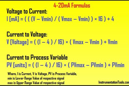
      Yes, Everyone uses direct formulas for conversion of current to percentage or current to process variable or other related conversations. But these all equations are derived from this standard formula only. Hope my article will be helpful.

      Reply
      • sudhakar says:
        April 18, 2016 at 1:32 am

        sir what about this formula 16*(20/100)+4

        Reply
      • Adaílton Samarone Nunes Ferreira says:
        March 22, 2024 at 4:12 am

        Obrigado, pelo ensinamentos cada ajuda e muito importante, obrigado e vamos estudar.

        Translated – Thank you, for the teachings, every help is very important, thank you and let’s study.

        Reply
  • Keith says:
    November 24, 2015 at 8:44 pm

    I’m trying to solve a liner equation with 4/20mA signal. Can you show me how set up the equation to solve? A value of 17.52mA is measured as the pv of 4/20 mA level loop. What is the URV, if the LRV corresponds to 1.2 meters depth and the PV is known to correspond to 2.9 meters?
    thanks Keith

    Reply
    • S Bharadwaj Reddy says:
      November 25, 2015 at 10:37 am

      Hi, URV is around 3.22 meters. Please click here for formula

      or

      Use the online Instrumentation calculator. Click Here

      Reply
    • Sk says:
      March 24, 2025 at 12:19 pm

      I have sensor and sensor range is 0 to 5000 they give out put 4-20mA . And I have temprature scanner in and it’s input is 0-5v DC. So how to calculate, and how to set span, minimum, maximum range in temprature scanner?

      Reply
  • Pravin Maheshkar says:
    April 18, 2017 at 7:13 am

    nice information…

    Reply
  • ANAS says:
    September 18, 2017 at 12:37 pm

    hiii sir,
    we have RECEIVED a flow transmitter make Fns FT 210-1A and it have an analog output of 4-20mA. BUT WE NEED A FLOW TRANSMITTER HAVING RANGE OF (6-20 m3/hr) as per spec. . Is there any idea about correlating or finding the flow rate range with this analog output.

    Reply
    • S Bharadwaj Reddy says:
      September 18, 2017 at 12:39 pm

      Hi, Please do re-calibrate your flow transmitter with your required range. Also check the flow transmitter measurable range.

      Reply
      • ANAS says:
        September 19, 2017 at 6:20 am

        thanks for your information.
        how can i confirm that this FT 210 can have range between 6-20 m3/hr?

        Reply
  • S Bharadwaj Reddy says:
    September 19, 2017 at 8:14 am

    Check your flow transmitter data sheet or Connect HART communicator to the FT and check Upper Sensor Limit (USL) and Lower Sensor Limit (LSL) which are usually in the mmH20 or related units. Check the Datasheet for the respective pressure values (mmH20) for the 6m3/hr and 20m3/hr and cross check with FT – USL & LSL values. Generally this range (6-20m3/hr) is quite low, so hopefully it will be within the range.

    Reply
    • ANAS says:
      September 19, 2017 at 10:13 am

      thank you very much for your kind information

      Reply
  • Krishan Kumar says:
    July 28, 2018 at 5:06 pm

    Hi,
    This formula is not working if value is in negative.
    Example: y={20-4/20-(-10)}×5+5

    Reply
  • Brian says:
    March 29, 2019 at 5:24 pm

    Hi sir ,

    very well explained ,

    I have develop a 4 to 20mA Caculator for Instrument Engineer , Check it out https://www.creatifwerks.com/4-to-20-ma-calculator-for-dcs-plc-programmer/

    Let me know if there are any Improvements can be Made. I will strive my best to make it the best 4 to 20 mA tools in the Internet

    So everyone can use it for free

    Reply
  • KEVIN says:
    October 28, 2023 at 12:34 pm

    I HAVE RTD SENSOR WHICH HAS THE RANGE OF -40 TO 120 . NOW THE TRANSMITTER SEND 10.5mA IT SHOWS 25.5c degree . can you please tell me the value of M & C . (SIGNAL GENERATE 4-20M=mA)

    Reply

Leave a Reply Cancel reply

Your email address will not be published. Required fields are marked *

Stay Connected

128.3kFollowersLike
69.1kFollowersFollow
210kSubscribersSubscribe
38kFollowersFollow

Categories

Explore More

How to Convert Cable Size from AWG to Inches
Formula for Linear % to Square root % conversion
Formula to Calculate 3-15psi from 4-20mA Current
PLC Raw Count Calculation for Pressure Transmitter
4-20mA Linear Conversion Calculation for VFD Drive (Formula)
Formula for Linear mA to Square root mA conversion
Calculate Flow Coefficient Kv of Solenoid Valve
How is Pressure Drop Calculated through a Valve ?

Keep Learning

PLC Problems Troubleshooting

PLC Problems Troubleshooting

Displacer Level Measurement Formula

Displacer Level Measurement Calculations

Linear to Square Root Extraction

Differential Pressure Transmitter

Calculate Process Variable from 4-20mA using Fraction of Measurement

4-20ma-formulas-and-examples

4-20mA Formulas and Examples

PLC analog input scaling

PLC Analog Input Scaling

Gas flow rate Formulas

Gas Flow Formulas

Relationship between Temperature Scales

Relationship between Temperature Scales

Learn More

Safety Relief Valve Questions & Answers

Safety Relief Valve Questions & Answers

Electrical Ladder Diagram Control using Timers Example

Electrical Ladder Diagram Control using Timers Example

Electronic Force Balance Pressure Transmitter

Electronic Force Balance Pressure Transmitter

Cable Shield

High-frequency Signal Cables

How to export in Vijeo Designer

Vijeo Designer software – Import and Export

Interference Immunity (EMC)

Basics of Electromagnetic compatibility (EMC)

Use of Isolator in Microwaves

Use of Isolator in Microwaves

Resistance Temperature Detectors Troubleshooting Tips

Resistance Temperature Detectors Troubleshooting Tips

Menu

  • About
  • Privacy Policy
  • Copyright

Quick Links

  • Learn PLC
  • Helping Hand
  • Part Time Job

YouTube Subscribe

Follow US
All rights reserved. Reproduction in whole or in part without written permission is prohibited.
Welcome Back!

Sign in to your account

Username or Email Address
Password

Lost your password?