A sensor is an input device that provides a usable output in response to the input measurand. A sensor is also commonly called a sensing element, primary sensor, or primary detector. The measurand is the physical parameter to be measured.
An input transducer produces an electrical output that is representative of the input measurand. Its output is conditioned and ready for use by the receiving electronics like PLC or DCS.
The receiving electronics can be an indicator, controller, computer, PLC, DCS etc. The term “transmitter,” as commonly used with industrial process control instrumentation, has a more narrow definition than those of a sensor or transducer:
A transmitter is a transducer that responds to a measured variable by means of a sensing element and converts it to a standardized transmission signal (like 4-20mA) that is a function only of the measured variable.
Transmitters can have any of several electrical connection schemes. The most common and easiest to use is the two-wire, loop-powered configuration.
This is generally the basic configuration for industrial process control systems when digital communication is not required.
As shown in Below Figure, only two wires are used to accommodate both power to the transmitter and output signal from the transmitter.
To facilitate a closed-loop control system, information from the process must be obtained before a controller can determine what action may be required by a control element. Some popular names for the sensing devices that provide the information are sensors, transducers, and/or transmitters.
The standard loop current is usually 4 to 20 mA. Important calibration parameters with a current loop are Zero, full scale, and span.
With the 4- to 20mA range, the loop current is normally 4 mA when the measurand or Process Variable is at zero, and 20 mA when the measurand or Process Variable is at full scale.
The difference between Zero and full scale, 16 mA, is called the span. Thus, the span corresponds to the indicated range of the measurand or Process Variable.
When considering a flow transmitter, for example, the range of the measurand or Process Variable is 0.0 to 100.0 m3/hr, corresponding to a 4- to 20-mA loop current (output span is then 16 mA); the output scaling factor is 0.16 mA/(m3/hr) (which is 100 m3/hr 16 mA).
Assumptions : Standard +24V DC with 20mA
In General PLC / DCS Analog Input card channel supplies more than 20mA current to power the loop.
The PLC / DCS Analog Input card transmits a standard +24 V DC, 20 mA signal to Power the Transmitter.
A one pair cable is used to power the transmitter and the same cable is used to receive the data in the 4-20mA current range.
Transmitter receives +24V DC, more than 20mA signal in the loop. A minimum +5V DC, 20mA signal is required to proper functioning of transmitter. In Practical there will be a voltage drop in the loop.
Transmitter have an inbuilt voltage regulator function which is used to regulate the loop current. The Transmitter will be configured with LRV, URV and other details of Process variable. The loop current will be varied / changed by the transmitter as per the measured Process variable.
The 4-20mA current will be converted into standard 1 – 5 V DC using a precision 250 ohms resistor. The Analog to Digital converter will be used to convert the voltage into digital signal which is used to indicate the Process Variable value in the DCS / PLC HMI.
Example:
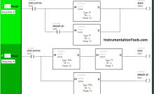
A Flow Transmitter with a range of 0 to 100 m3/hr. Transmitter indicates 0 m3/hr as there is no flow in the line. DCS / PLC powers the transmitter with +24V DC, 20mA.
As Process Variable is 0 m3/hr, the transmitter regulates the loop current to 4mA and its equivalent voltage is 1 V DC which is measured by A/D Converter which indicates 0% of Process Variable.
Note: The loop current will be same either at starting or end or any point in the loop. For easy understanding only, both 20mA & 4 mA signals are shown in the animation.
In Practical, When we measure the current at any point in the loop, the transmitter output current will be found i.e. 4mA as per above figure, so just assume DCS/PLC system powers the loop with +24V DC, 20mA (generally systems supplies more than 20mA) while transmitter regulates the loop current within 4mA to 20mA as per its configuration & real time process variable value.
If you want to measure the PLC/DCS loop power i.e. 20mA (as per above figure) signal then disconnect the transmitter from the loop & Connect the multimeter in series with DCS/PLC to measure the loop current. And the one pair cable is a twisted pair cable.
Same Principle applies. The Transmitter adjust the loop current as per the Process Variable.
The only difference is the transmitter sensing element changes its output as process variable varied from 0% to 50%. The transmitter regulates the loop current as per the sensing element.
Example:
Process variable indicates 50 m3/hr. Transmitter regulates output to 12mA in the loop as per the configured range and measured process variable and its equivalent voltage is 3 V DC which is measured by A/D Converter which indicates 50% of Process Variable.
Same Principle applies. The Transmitter adjust the loop current as per the Process Variable.
The only difference is the transmitter sensing element changes its output as process variable varied from 50% to 100%. The transmitter regulates the loop current as per the sensing element.
Example:
Process variable indicates 100 m3/hr. Transmitter regulates outputs to 20mA in the loop as per the configured range and measured process variable and its equivalent voltage is 5 V DC which is measured by A/D Converter which indicates 100% of Process Variable.
Although almost any type of transducer can be configured as a transmitter, the most common types for industrial process control comprise measurands or Process Variables like temperature, pressure, flow, level etc.
Transmitters for measuring other parameters will have the same possibilities for connection and communication methods, with the main differences being in the sensing element design of transmitter and electronic equipment will be same with slightly software modification.
The main advantage of a two-wire loop is that it minimizes the number of wires needed to run both power and signal. The use of a current loop to send the signal also has the advantages of reduced sensitivity to electrical noise and to loading effects.
The electrical noise is reduced because the two wires are run as a twisted pair, ensuring that each of the two wires receives the same vector of energy from noise sources, such as electro- magnetic fields due to a changing current in a nearby conductor or electric motor.
Since the receiving electronics connected to the transmitter is designed to ignore common-mode signals, the resulting common-mode electrical noise is ignored.
The sensitivity to loading effects is reduced because the current in the twisted pair is not affected by the added resistance of long cable runs.
A long cable or other series resistance will cause a greater voltage drop but does not affect the current level as long as enough voltage compliance is available in the circuit to supply the signal current.
Also Read : How PLC controls a Motor ?
The circuit compliance to handle a given voltage drop from additional loop devices depends on the transmitter output circuit and on the power supply voltage.
The typical power supply for industrial transmitters is +24 VDC. If 6 volts, for example, are needed to power the transmitter and its output circuit, then 18 volts of compliance remain to allow for wire resistance, load resistance, voltage drops across intrinsic safety (IS) barriers and remote displays, etc.
Where the current loop signal is connected to the main receiving equipment (PLC/DCS) or data acquisition system, a precision load resistor of 250 ohms is normally connected.
This converts the 4 to 20 mA current signal into a 1 to 5 volt signal, since it is standard practice to configure the analog-to-digital converter of the receiving equipment (PLC/DCS) as a voltage-sensing input.
In contrast to the two-wire current-loop configuration, some current-loop devices require a three or four wire connections. These are not loop powered and therefore have a separate means for providing power by adding one or two more wires.
In a four-wire configuration, the current-loop wires can be a twisted pair, and the power supply wires a separate twisted pair. This preserves the ability to reject electrical and magnetic common-mode interference. This is not so effective in a three-wire configuration due to the common connection for the return current path.
Typically, though, when an instrumentation engineer specifies a current-loop transmitter for industrial process control, it is assumed that a two-wire, loop-powered 4 to 20 mA device is intended.
Other data signals may also be impressed upon the same wire pair, or alternatively, various digital communication techniques can be used instead of a current loop, if required.
If you liked this article, then please subscribe to our YouTube Channel for Instrumentation, PLC, and SCADA video tutorials.
You can also follow us on Facebook and Twitter to receive daily updates.
Read Next:
In this example, we will learn batch mixing with PLC ladder logic program using timer…
This PLC example on manufacturing line assembly is an intermediate-level PLC program prepared for the…
In this article, you will learn the PLC programming example with pushbutton and motor control…
This article teaches how to convert Boolean logic to PLC programming ladder logic with the…
In this article, you will learn the PLC programming example on timers function block using…
Design a program for PLC pump control such that the pump must be turned ON…

View Comments
very good info
Excellent Article. No one is providing information but you Mr.Bharadwaj - you are great. Thank you for everything.
Thanks a lot...great information...
thanks sir
Very useful thanks
I need print options
Thanks sir
Please let me know the print options to save this valuable information
I am working on it. As soon as possible the options will be configured.
Thank you very much.
Thank you so much sir
Excellent information.