2-way solenoid valves operate in a manner analogous to single-pole single-throw (SPST) electrical switches: with only one path for flow.
Solenoid valve symbols often appear identical to fluid power valve symbols, with “boxes” representing flow paths and directions between ports in each of the valve’s states.
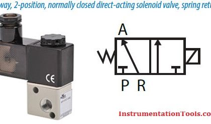
Like electrical switches, these valve symbols are always drawn in their “normal” (resting) state, where the return spring’s action determines the valve position:
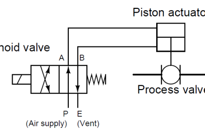
2-way Solenoid Valve


A good way to make sense of these “box” valve symbols is to imagine the boxes sliding back and forth as the actuating elements work.
For example, the two boxes in a normally-closed solenoid valve symbol may be thought of in terms of being pushed to the left by the spring when de-energized and pushed to the right by the solenoid’s force when energized.
Here, the color grey de-emphasizes the unselected box in each of the valve’s two states:

As with electrical switches in schematic diagrams, fluid control valve symbols are always drawn in their “normal” (resting) states.
For example, a normally-closed valve will always be drawn so that the box with the blocked ports aligns with the tubes leading to and from the valve.
What you see in the above illustration are “dramatized” symbols, highlighting the valve’s action by color and by re-positioning the boxes, strictly for the purpose of making it easier for you to grasp the concept.
This sort of coloring and re-positioning is never shown in a real schematic diagram. In a fluid control schematic, it is left to the reader to visualize the valve symbol boxes moving to and fro, determining the flow path of fluid through the valve.
Unlike electrical switches, of course, the terms open and closed have opposite meanings for valves.
An “open” electrical switch constitutes a break in the circuit, ensuring no current; an “open” valve, by contrast, freely allows fluid flow through it.
A “closed” electrical switch has continuity, allowing current through it; a “closed” valve, on the other hand, shuts off fluid flow.
The arrow inside a solenoid valve symbol actually denotes a preferred direction of flow.
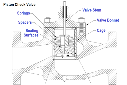
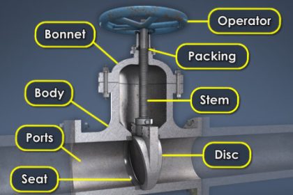
Most solenoid valves use a “globe” or “poppet” style of valve element, where a metal plug covers up a hole (called the “seat”).
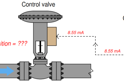
Process fluid pressure should be applied to the valve in such a way that the pressure difference tends to hold the solenoid valve in its “normal” position (the same position as driven by the return spring).
Otherwise (below note point), enough fluid pressure might override the return spring’s action, preventing the valve from achieving its “normal” state when de-energized.
Thus, we see that the label “2-way” does not refer to two directions of flow as one might assume, but rather two ports on the valve for fluid to travel through.
Some solenoid valves are designed in such a way that the direction of fluid flow through them is irrelevant.
In such valves, the arrow symbols will be double-headed (one head at each end, pointing in opposite directions) to show the possibility of flow in either direction.

Note : One could argue that enough fluid pressure could override the solenoid’s energized state as well, so why choose to have the fluid pressure act in the direction of helping the return spring?
The answer to this (very good) question is that the solenoid’s energized force greatly exceeds that of the return spring.
This is immediately obvious on first inspection, as the solenoid must be stronger than the return spring or else the solenoid valve would never actuate!
Furthermore, the solenoid’s force must be significantly stronger than the spring, or else the valve would open rather slowly.
Fast valve action demands a solenoid force that greatly exceeds spring force. Realizing this, now, we see that the spring is the weaker of the two forces, and thus it makes perfect sense why we should use the valve in such a way that the process pressure helps the spring: the solenoid’s force has the best chance of overcoming the force on the plug produced by process pressure, so those two forces should be placed in opposition, while the return spring’s force should work with (not against) the process pressure.
Credits : by Tony R. Kuphaldt – under the terms and conditions of the Creative Commons Attribution 4.0 International Public License