Example of a PLC control system program with 1 button To activate 4 different machines with timer and counter functions in CX-Programmer.
Introduction
This article discusses the concept of a sequential system that is operated manually.
1 Button To Activate 4 Different Machines
This system has 4 buttons, the START_SYSTEM (0.00) button is used to Turn On the system (standby state), the STOP_SYSTEM (0.01) button is used to Turn Off the system, the RUN_SYSTEM (0.02) button is used to Run the system, and RESET_SYSTEM (0.03) button is used to Reset the sequence counter.
The system will be ON (standby state) when the START_SYSTEM (0.00) button is pressed and then the memory bit SYSTEM_ON (W0.00) is ON. Because it uses Latching, the memory bit SYSTEM_ON (W0.00) remains ON even though the START_SYSTEM (0.00) button has been Released. The memory bit SYSTEM_ON (W0.00) will be OFF if the STOP_SYSTEM (0.01) button is Pressed.
This program has 3 sequences stored in memory word SEQUENCE (D0). In sequence 1, when the RUN_SYSTEM (0.02) button is pressed, the value in memory word SEQUENCE (D0) becomes “1” and Output MACHINE_1 (100.00) will be ON. The MACHINE_1 (100.00) Output will be ON for 15 seconds then OFF because it uses Timer instruction TIMER_1 (T0000).
In sequence 2, when RUN_SYSTEM (0.02) button is Pressed again, the value in memory word SEQUENCE (D0) increases (+1) to “2” and Output MACHINE_2 (100.01) will be ON. The MACHINE_2 (100.01) Output will be ON for 10 seconds and then OFF because it uses Timer instruction TIMER_2 (T0001).
In sequence 3, when the RUN_SYSTEM (0.02) button is Pressed again, the value in memory word SEQUENCE (D0) increases (+1) to “3” and Output MACHINE_3 (100.02) will be ON. The MACHINE_3 (100.02) Output will be ON and then OFF because it uses Timer instruction TIMER_3 (T0002). After Timer TIMER_3 (T0002) has finished counting for 5 seconds, Output MACHINE_3 (100.02) will be OFF and the sequence will be Reset to “0”.
When the RESET_SYSTEM (0.03) button is pressed, the word SEQUENCE (D0) memory is reset to “0” and the system returns to the standby state.
IO Details
| Comment | Input (I) | Output(Q) | Memory Bits | Memory Word | Timers |
| START_SYSTEM | 0.00 | ||||
| STOP_SYSTEM | 0.01 | ||||
| RUN_SYSTEM | 0.02 | ||||
| RESET_SYSTEM | 0.03 | ||||
| MACHINE_1 | 100.00 | ||||
| MACHINE_2 | 100.01 | ||||
| MACHINE_3 | 100.02 | ||||
| TIMER_1 | T0000 | ||||
| TIMER_2 | T0001 | ||||
| TIMER_3 | T0002 | ||||
| SYSTEM_ON | W0.00 | ||||
| SEQUENCE | D0 |
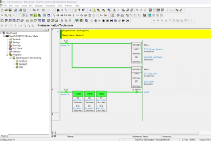
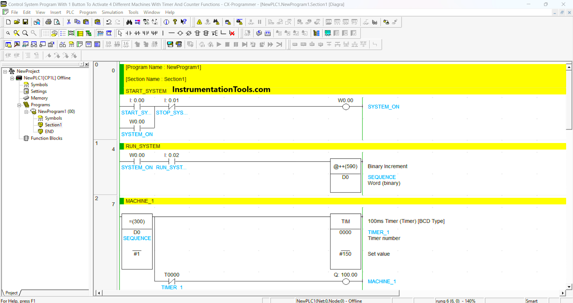
CX-Programmer Logic
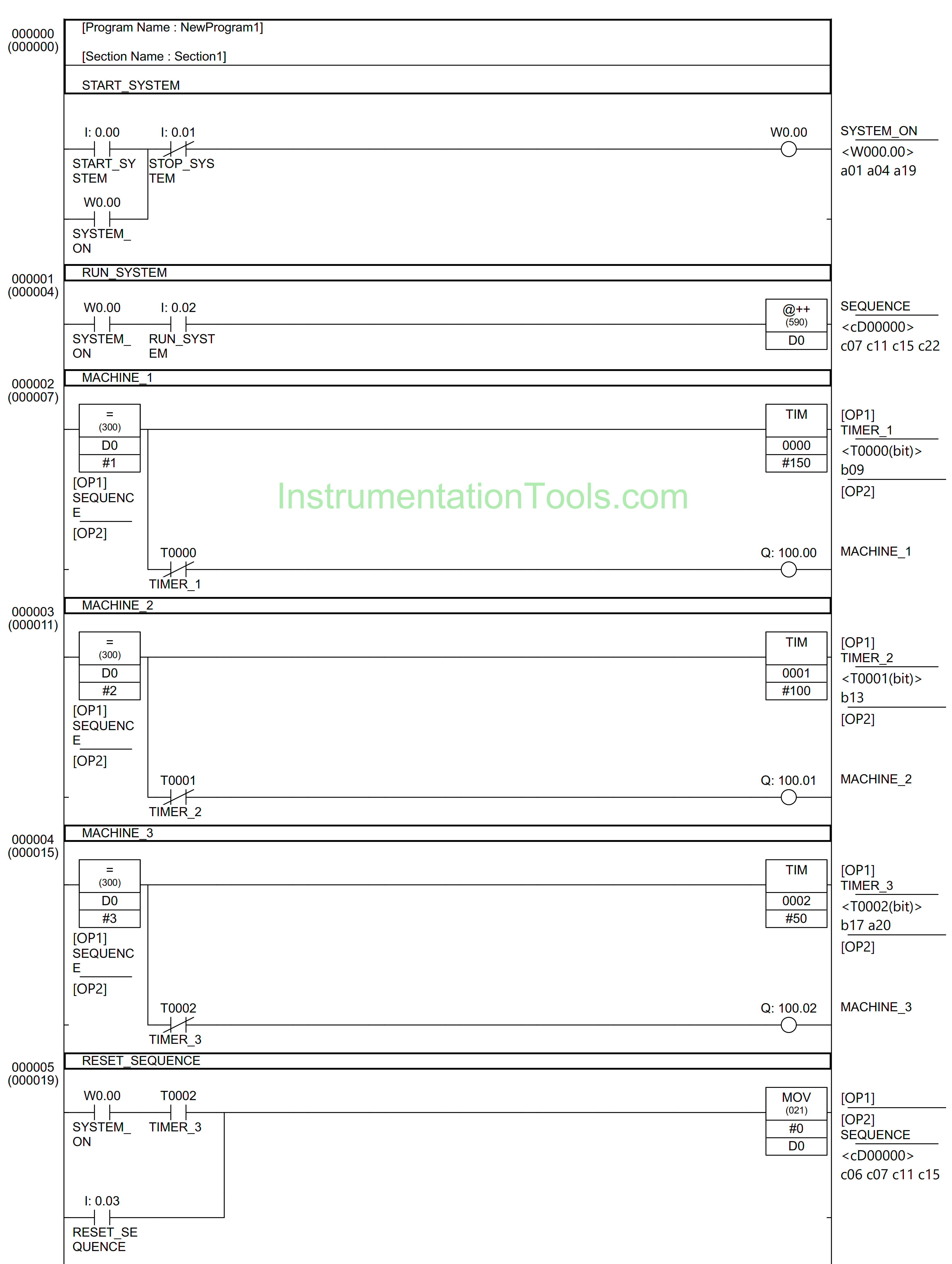
RUNG 0 (START_SYSTEM)
In this Rung, when the START_SYSTEM (0.00) button is Pressed, the memory bit SYSTEM_ON (W0.00) changes to an ON state. Because it uses latching, the memory bit SYSTEM_ON (W0.00) remains ON even though the START_SYSTEM (0.00) button has been Released. The memory bit SYSTEM_ON (W0.00) will be OFF if the STOP_SYSTEM (0.01) button is Pressed.
RUNG 1 (RUN_SYSTEM)
When the Normally Open contact of memory bit SYSTEM_ON (W0.00) is in a HIGH state and the RUN_SYSTEM (0.02) button is pressed, the Binary Increment Instruction will add (+1) data to the memory word SEQUENCE (D0).
RUNG 2 (MACHINE_1)
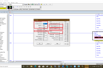
When the value in the memory word SEQUENCE (D0) is equal to “1”, then Output MACHINE_1 (100.00) will be ON and the Timer instruction TIMER_1 (T0000) will start counting up to 15 seconds.
When Timer instruction TIMER_1 (T0000) reaches “Set value” then the Output MACHINE_1 (100.00) becomes OFF due to the Interlock from TIMER_1 (T0000).
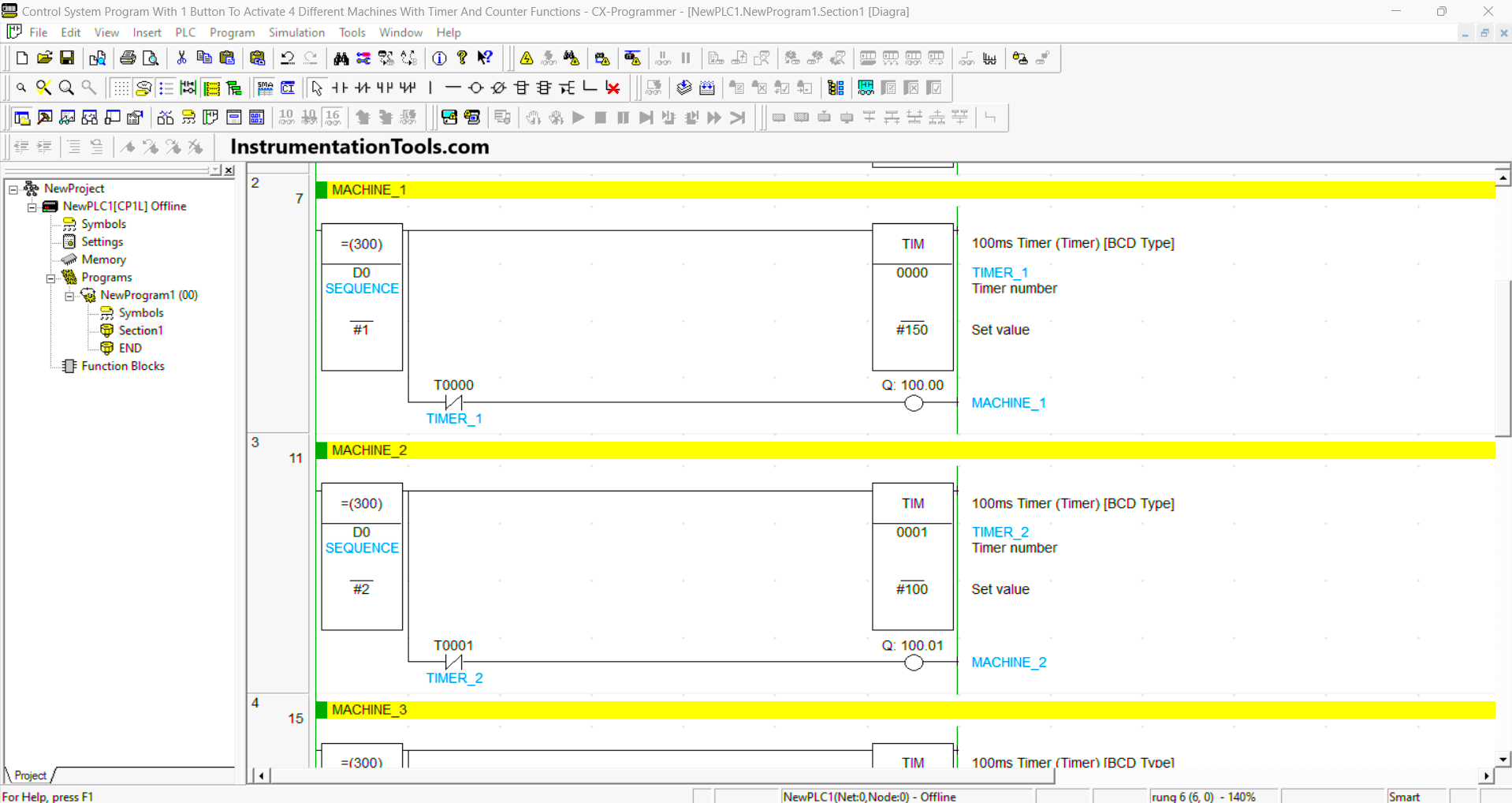
RUNG 3 (MACHINE_2)
When the value in the memory word SEQUENCE (D0) is equal to “2”, then Output MACHINE_2 (100.01) will be ON and the Timer instruction TIMER_2 (T0001) will start counting up to 10 seconds.
When Timer instruction TIMER_2 (T0001) reaches “Set value” then the Output MACHINE_2 (100.01) becomes OFF due to the “Interlock” from TIMER_2 ( T0001).
RUNG 4 (MACHINE_3)
When the value in the memory word SEQUENCE (D0) is equal to “3”, then Output MACHINE_3 (100.02) will be ON and the Timer instruction TIMER_1 (T0002) will start counting up to 5 seconds.
When Timer instruction TIMER_3 (T0002) reaches “Set value”, then the Output MACHINE_3 (100.02) becomes OFF due to the “Interlock” from TIMER_3 (T0002).
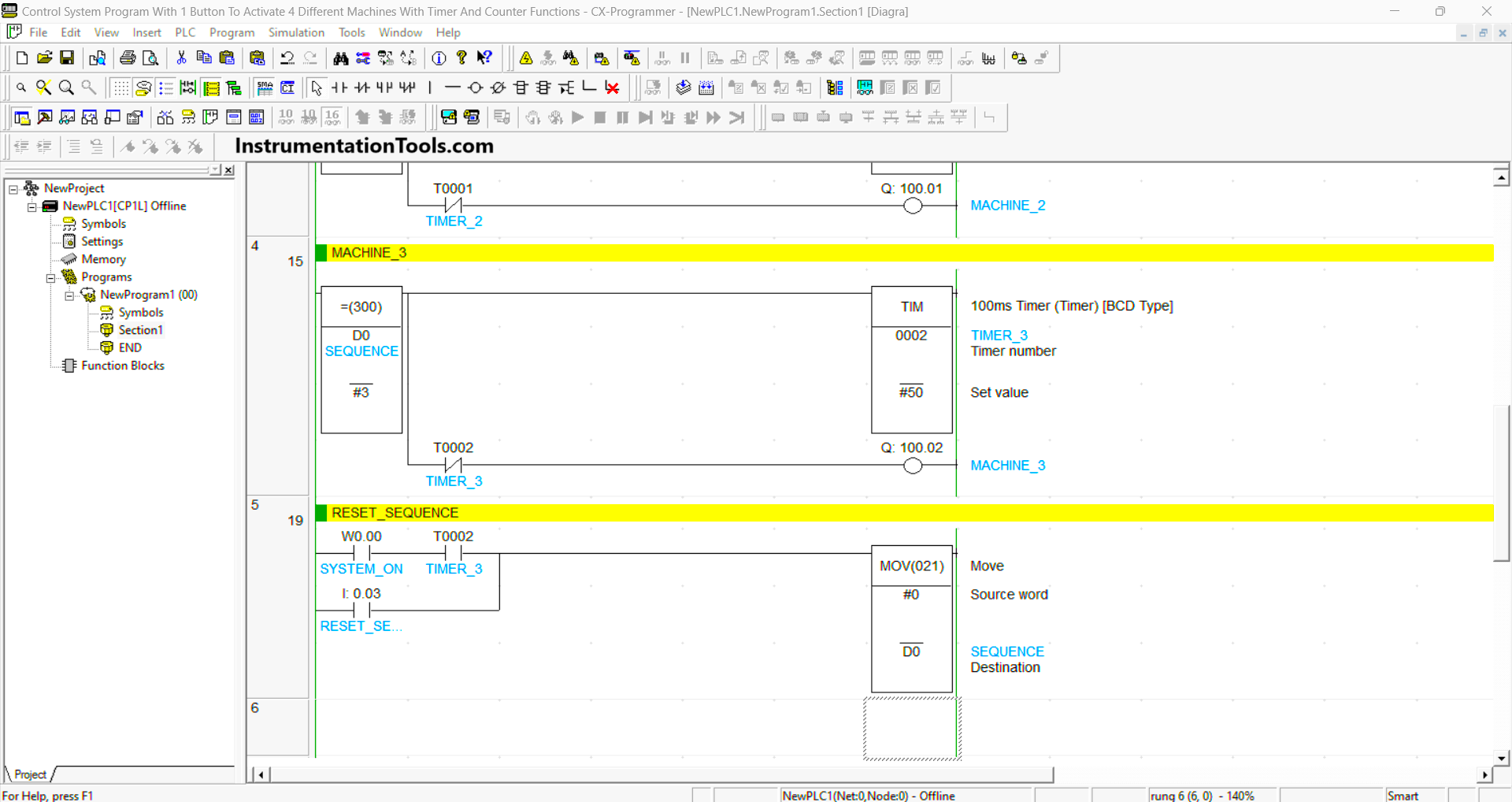
RUNG 5 (RESET_SEQUENCE)
In this Rung, when the Normally Open contact of memory bit SYSTEM_ON (W0.00) and TIMER_3 (T0002) in the HIGH state, then memory word SEQUENCE (D0) becomes the value “0” because the MOV(021) instruction moves value “0” to memory word SEQUENCE (D0).
Or, when the RESET_SYSTEM (0.03) button is pressed, then the memory word SEQUENCE (D0) becomes “0”.
Read Next:
- OMRON PLC Tutorial: Car Parking System
- PLC Program for Controlling a Water Pump
- CX-Programmer Products Sorting & Counting
- Real-Time Clock in Omron CX Programmer
- PLC Program for Ceramic Burning Oven