Inst ToolsInst ToolsInst Tools
  • Courses
  • Automation
    • PLC
    • Control System
    • Safety System
    • Communication
    • Fire & Gas System
  • Instrumentation
    • Design
    • Pressure
    • Temperature
    • Flow
    • Level
    • Vibration
    • Analyzer
    • Control Valve
    • Switch
    • Calibration
    • Erection & Commissioning
  • Interview
    • Instrumentation
    • Electrical
    • Electronics
    • Practical
  • Q&A
    • Instrumentation
    • Control System
    • Electrical
    • Electronics
    • Analog Electronics
    • Digital Electronics
    • Power Electronics
    • Microprocessor
  • Request
Search
  • Books
  • Software
  • Projects
  • Process
  • Tools
  • Basics
  • Formula
  • Power Plant
  • Root Cause Analysis
  • Electrical Basics
  • Animation
  • Standards
  • 4-20 mA Course
  • Siemens PLC Course
Reading: Animation of Electromagnetic Relay
Share
Notification Show More
Font ResizerAa
Inst ToolsInst Tools
Font ResizerAa
  • Courses
  • Design
  • PLC
  • Interview
  • Control System
Search
  • Courses
  • Automation
    • PLC
    • Control System
    • Safety System
    • Communication
    • Fire & Gas System
  • Instrumentation
    • Design
    • Pressure
    • Temperature
    • Flow
    • Level
    • Vibration
    • Analyzer
    • Control Valve
    • Switch
    • Calibration
    • Erection & Commissioning
  • Interview
    • Instrumentation
    • Electrical
    • Electronics
    • Practical
  • Q&A
    • Instrumentation
    • Control System
    • Electrical
    • Electronics
    • Analog Electronics
    • Digital Electronics
    • Power Electronics
    • Microprocessor
  • Request
Follow US
All rights reserved. Reproduction in whole or in part without written permission is prohibited.
Inst Tools > Blog > Animation > Animation of Electromagnetic Relay

Animation of Electromagnetic Relay

Last updated: March 4, 2021 4:58 pm
Editorial Staff
Animation Control Systems PLC Tutorials
2 Comments
Share
4 Min Read
SHARE

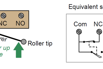
When a voltage is applied to the coil, a current passes through it and this creates a magnetic circuit which includes the core, armature and the yoke.

Contents
Animation of Electromagnetic RelaySimple Relay Schematic :Relay Schematic : When Switch Not PressedRelay Schematic : When Switch Pressed

The core attracts the armature, which pivots and presses the push rod against the common contact, breaking the electrical connection with one contact and making the electrical connection with the other contact. When the voltage is removed from the coil the magnetic attraction of the armature to the core ceases.

A spring then returns the contacts, pushrod and armature to the initial position. In this example, the common contact also acts as the spring, but in other relays, a separate spring is employed.

Animation of Electromagnetic Relay

Animation of Electromagnetic Relay

The above animation shows that when we apply a voltage to the relay coil, the Relay contacts will change.

For example the Normally Open (NO) becomes Normally Closed (NC) and similarly the Normally Closed (NC ) becomes Normally Open (NO). When we remove the applied voltage to the relay coil then the relay contacts again comes into default state.

Simple Relay Schematic :

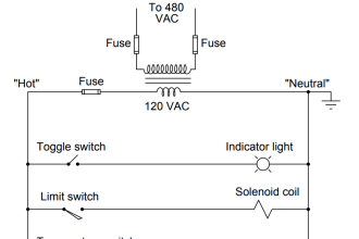
Design a relay (CR1) circuit which controls two lamps, one is Red lamp (R) and another is Green Lamp (G). These lamps will be controlled by using a single switch (S).

When switch is pressed then Red lamp will be ON and Green lamp will be ON during switch de-energised state.

Relay Wiring Schematic

Relay Schematic : When Switch Not Pressed

Relay Schematic Animation

Circuit Operation :

  • When Switch S in Open state
  • Relay Coil CR1 will be De-energized
  • Relay Contact CR1-1 will be Open (Here Relay NO contact is using in the circuit.)
  • Red Lamp will be OFF as relay contact CR1-1 is Normally Open (NO). so circuit open and no current flow.
  • Relay Contact CR1-2 will be Closed (Here Relay NC contact is using in the circuit.)
  • Green Lamp will be ON as relay contact CR1-2 is Normally Closed (NC). so circuit closes and there is a current flow.

Relay Schematic : When Switch Pressed

Animation of Relay Ladder Logic

Circuit Operation :

  • When Switch S in Closed state
  • Relay Coil CR1 will be Energized
  • Relay Contact CR1-1 will be Closed (Here Relay NO contact is using in the circuit.)
  • Red Lamp will be ON as relay contact CR1-1 Normally Open (NO) contact becomes Normally closed as Relay is energized.
  • Relay Contact CR1-2 will be Open (Here Relay NC contact is using in the circuit.)
  • Green Lamp will be OFF as relay contact CR1-2 Normally Close (NC) contact becomes Normally Open as Relay is energized.

If you liked this article, then please subscribe to our YouTube Channel for PLC and SCADA video tutorials.

You can also follow us on Facebook and Twitter to receive daily updates.

Read Next:

Switch Types and Common Terminology

Why we use NAMUR Output Sensor?

Pressure Switch to control two lamps

Sink or Source? PNP or NPN

Don't Miss Our Updates
Be the first to get exclusive content straight to your email.
We promise not to spam you. You can unsubscribe at any time.
Invalid email address
You've successfully subscribed !

Continue Reading

PLC Program for Flow Totalizer
Safety PLC Coding Practices – Programming Recommendations
Network Operating System
How to Read the PLC Datasheet? – Important Notes About PLC
2-wire Transmitters Current Loops
CODESYS HMI Interface
Share This Article
Facebook Whatsapp Whatsapp LinkedIn Copy Link
Share
2 Comments
  • Deepak says:
    July 9, 2017 at 4:06 pm

    Dear sir I need help in configuration of pid loops in Siemens s7 200 smart PLC using microwin software

    Reply
  • Ryszard says:
    July 11, 2017 at 7:13 pm

    Great engineering imformation. I have a question about relay schematic: when switch is pressed: Are NO relay CR1-1 has good symbol?

    Reply

Leave a Reply Cancel reply

Your email address will not be published. Required fields are marked *

Stay Connected

128.3kFollowersLike
69.1kFollowersFollow
210kSubscribersSubscribe
38kFollowersFollow

Categories

Explore More

Why 24 Volts DC Power Supply is used? – Industrial Automation Systems
Difference between PLC and HMI
Can a PLC Function Without an HMI or SCADA?
I&C Engineer Roles & Responsibilities – Instrumentation Design
30 Concerns for Process Control Systems Philosophy
PLC Logic: Control Spray Nozzle, Fans, and Puncher
Connecting Faceplate to PLC Project – HMI Tutorial
PLC to Start or Stop 3 Machines using 1 Switch Program

Keep Learning

Delta WPL Soft Counter

Delta PLC Counter with Comparison

PLC Digital Inputs

PLC Digital Input and Digital Output Modules

Overview of Industrial Control Systems

Overview of Industrial Control Systems

Lights with Adjustable Timers PLC Programming

Flip-Flop PLC Programming: Lights with Adjustable Timers

Omron PLC Example

Design a Water Pump PLC Program using CX-Programmer

Conveyor and Puncher PLC Program

Toggle Switch & Sensor: Conveyor and Puncher PLC Program

Industrial Gas Detection Systems

PLC based Gas Detection System using Ladder Logic Project

Ladder Logic Counters Instruction

Up Counter PLC Program

Learn More

Zener Diode Regulator

Zener Diode Voltage Regulators

Absolute Pressure Gauges Principle

Absolute Pressure Gauges Principle

Advantages and Disadvantages of Network Topology

Advantages and Disadvantages of Air Blast Circuit Breakers

Difference Between Robotics and Automation

Difference Between Robotics and Automation

Microwave Barrier Level Switch Working Principle

Electromagnetic Fields Objective Questions

Electromagnetic Field Theory Questions and Answers

On Delay Timer TON in Tia Portal

Timers in PLC Programming – Siemens Tia Portal Tutorials

Top PLC Manufacturers

Top PLC Manufacturers

Menu

  • About
  • Privacy Policy
  • Copyright

Quick Links

  • Learn PLC
  • Helping Hand
  • Part Time Job

YouTube Subscribe

Follow US
All rights reserved. Reproduction in whole or in part without written permission is prohibited.
Welcome Back!

Sign in to your account

Username or Email Address
Password

Lost your password?