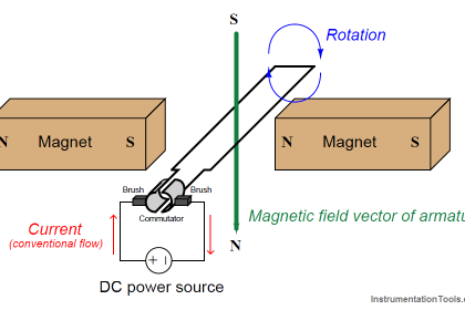
The basic principle of an AC induction motor is that one or more out-of-phase AC (sinusoidal) currents energize sets of electromagnet coils (called stator coils or windings) arranged around the circumference of a circle. As these currents alternately energize the coils, a magnetic field is produced which “appears” to rotate around the circle. This rotating magnetic field is not unlike the appearance of motion produced by an array of chaser lights blinking on and off in sequence: although the bulbs themselves are stationary, the out-of-phase sequence of their on-and-off blinking makes it appear as though a pattern of light “moves” or “chases” along the length of the array. Likewise, the superposition of magnetic fields created by the out-of-phase coils resembles a magnetic field of constant intensity revolving around the circle. The following images show how the magnetic field vector (the red arrow) is generated by a superposition of magnetic poles through one complete cycle (1 revolution), viewing the images from left to right, top to bottom (the same order as you would read words in an English sentence).
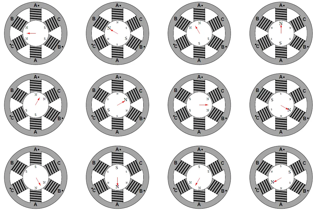
It should come as no surprise that the combined effect of these three-phase currents will be to create a resultant magnetic field vector rotating in a particular direction. After all, this is precisely how three-phase electric power is generated: by spinning a single magnet at the center of three sets of coils offset by 120 degrees. The rotating magnetic field generated by the stator windings of a three-phase motor is merely a reproduction of the rotor’s magnetic field inside the generator supplying the three-phase power!
If a permanent magnet were placed within the center of this machine on a shaft such that it was free to rotate, the magnet would spin at the exact same speed as the rotating magnetic field. If the magnetic field completes one full revolution in 1/60 of a second, the rotating speed of the magnet will be 60 revolutions per second, or 3600 revolutions per minute (3600 RPM). Since the magnet follows in lock-step with the rotating magnetic field, its rotational speed is said to be synchronous. We would thus identify this motor as a synchronous AC motor.
If an electrically conductive object were placed within the center of this same machine on a shaft such that it was free to rotate, the relative motion between the rotating magnetic field and the conductive object (rotor) would induce electric currents in the conductive object, producing magnetic fields of their own. Lenz’s Law tells us that the effect of these induced magnetic fields would be to try to oppose change: in other words, the induced fields react against the rotating magnetic field of the stator coils in such a way as to minimize the relative motion. This means the conductive object would begin to rotate in the same direction as stator’s rotating magnetic field, always trying to “catch up” to the rotating magnetic field. However, the conductive rotor could never exactly match the speed of the rotating magnetic field as in the case of a synchronous motor. If the rotor ever did achieve synchronous speed, there would no longer be any relative motion between the rotor and the rotating magnetic field, which means the induction would cease. No induction would mean no electric currents induced in the rotor, which would mean no reactive magnetic field, which would mean no torque to motivate the rotor. Thus, the electrically conductive rotor’s speed must always slightly lag (“slip”) behind the rotating magnetic field’s synchronous speed in order to experience induction and thereby be able to create a torque. We call this type of motor an induction AC motor.
It may come as a surprise for some to learn that any conductive object – ferromagnetic or not – will experience a torque when placed inside the rotating magnetic field generated by the stator coils. So long as the object is electrically conductive, electromagnetic induction will ensure the creation of electric currents in the rotor, and these currents will produce their own magnetic fields which react against the stator’s rotating magnetic field to produce a torque on the rotor.
The effect of Lenz’s Law between a magnet and a conductive object may be demonstrated by using a powerful permanent magnet and a strip of light-weight aluminum foil. Aluminum, of course, is electrically conductive but non-magnetic. However, despite the lack of magnetic attraction between the magnet and the foil, the foil will nevertheless experience a motive force if the magnet is swept past its surface rapidly, due to Lenz’s Law:
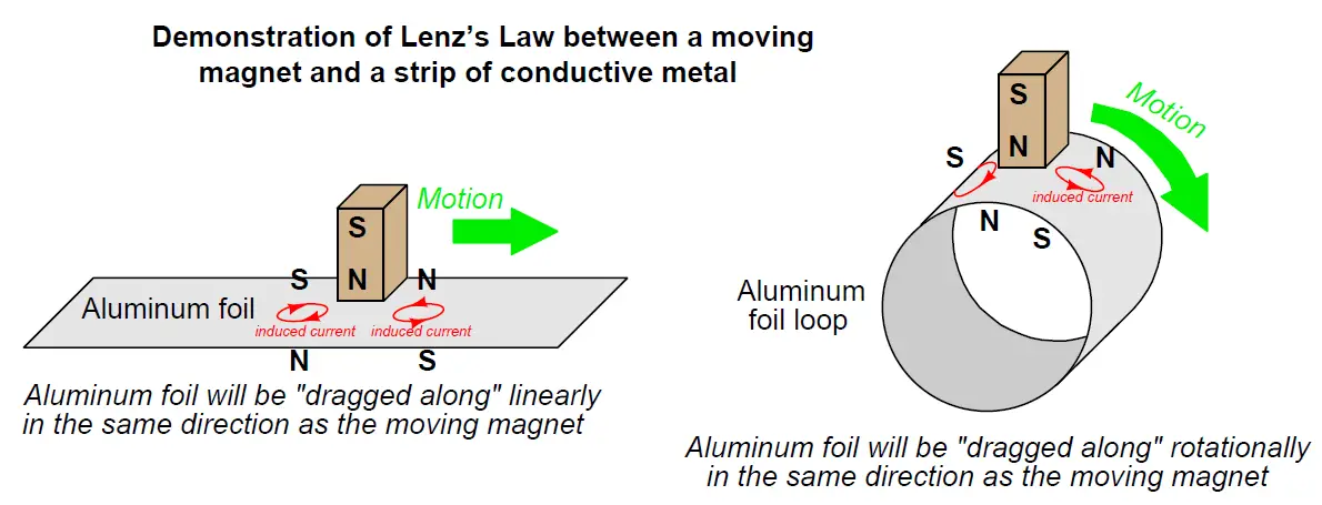
This very same principle is what makes an induction AC motor function: a rotating magnetic field induces electric currents in an electrically-conductive rotor, which then spins in the same direction as the magnetic field. An induction motor’s rotor can never achieve synchronous speed on its own, for if it ever did the induction would cease due to a lack of relative motion between the rotating magnetic field and the rotor. The same is true of the aluminum foil strip experiments: the foil strip can never fully “catch up” to the moving magnet, for if it ever did the induction would cease and the motive force would disappear. Thus, induction machines always spin a bit slower than synchronous speed.
A typical “two-pole” (Note 1 ) induction motor operating at a power line frequency of 60 Hz has a synchronous speed of 3600 RPM (i.e. the rotating magnetic field is spinning 60 revolutions per second), but the rotor may only achieve a full-load speed of approximately 3540 RPM. Similarly, a typical “four-pole” induction motor with a synchronous speed of 1800 RPM (Note 2 )may only attain a rotor speed of approximately 1760 RPM.
Note 1 : Two magnetic poles in the stator per phase, which is the lowest number possible because each phase naturally produces both a “north” and a “south” pole when energized. In the case of a three-phase induction or synchronous motor, this means a total of six magnetic stator poles.
Note 2 : Doubling the number of magnetic poles increases the number of AC power cycles required for the rotating magnetic field to complete one full revolution. This effect is not unlike doubling the number of light bulbs in a chaser light array of fixed length, making it seem as though the light sequence is moving slower because there are more bulbs to blink along the same distance.
Induction motors are by far the most popular design in industry. The most common variant of the induction motor is the so-called squirrel-cage design, where the rotor is made up of aluminum bars joining two aluminum “shorting rings,” one at either end of the rotor. Ferrous metal (iron alloy) fills the spaces between the rotor bars to provide a lower-reluctance magnetic “circuit” between stator poles than would otherwise be a large air gap if the rotor were simply made of aluminum. If the ferrous metal were removed from the rotor, the remaining aluminum bars and shorting rings would resemble the cage-wheel exercise machine used by hamsters and other pet rodents, hence the name.
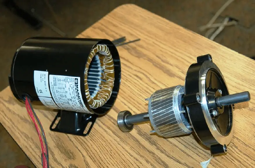
A photograph of a small, disassembled three-phase AC induction “squirrel-cage” motor is shown here, revealing the construction of the stator coils and the rotor:
Given the extremely simple construction of AC induction motors, they tend to be very reliable. So long as the stator coil insulation is not damaged by excessive moisture, heat, or chemical exposure, these motors will continue to operate indefinitely. The only “wearing” components are the bearings supporting the rotor shaft, and those are easily replaced. Starting a three-phase induction motor is as simple as applying full power to the stator windings. The stator coils will instantly produce a magnetic field rotating at a speed determined by the frequency of the applied AC power, and the rotor will experience a large torque as this high-speed (relative to the rotor’s stand-still speed of zero) magnetic field induces large electric currents in it. As the rotor comes up to speed, the relative speed between the rotating magnetic field and the rotating rotor diminishes, weakening the induced currents and also the rotor’s torque. One way to “model” an AC induction motor is to think of it as an AC transformer with a short-circuited, movable secondary winding. When full power is first applied, the initial current drawn by the stator (primary) windings will be very large, because it “sees” a short-circuit in the rotor (secondary) winding. As the rotor begins to turn, however, this short-circuit draws less and less current until the motor reaches full speed and the line current approaches normal. As with a transformer, where a reduction in secondary current (from a load change) results in a reduction in primary current, the reduction in induced rotor current (from reduced slip speed) results in a reduction in stator winding current.
The huge surge of current at start-up time (as much as ten times the normal running current!) is called inrush current, causing the rotor to produce a large mechanical torque. As the rotor gains speed, the current reduces to a normal level, with the speed approaching the “synchronous” speed of the rotating magnetic field. If somehow the rotor achieves synchronous speed (i.e. the slip speed becomes zero), stator current will fall to an absolute minimum. If a mechanical power source “overdrives” a powered induction motor, forcing it to spin faster than synchronous speed, it will actually begin to function as a generator and source electrical power.
Any mechanical load causing the motor to spin slower likewise causes the stator windings to draw more current from the power supply. This is due to the greater slip speed causing stronger currents to be induced in the rotor. Stronger rotor currents equate to stronger stator currents, just like a transformer where a heavier load on the secondary winding causes greater currents in both secondary and primary windings.
Reversing the rotational direction of a three-phase motor is as simple as swapping any two out of three power conductor connections. This has the effect of reversing the phase sequence of the power “seen” by the motor.
An interesting problem to consider is whether it is possible to make an AC induction motor function on single-phase power rather than polyphase power. After all, it is the three-step phase sequence of three-phase AC power that gives the stator windings’ magnetic field its definite rotational direction. If we have only one sine wave supplied by the AC power source, is it possible to generate a truly rotating magnetic field? At best, it seems all we could ever produce with single-phase AC power is a pulsing or “blinking” magnetic field. If you imagine a string of light bulbs blinking on and off 180o out of phase (i.e. ABABABAB), one could argue the sequence is marching from A to B, or alternatively from B to A – there is no definite direction to the lights’ “motion.”
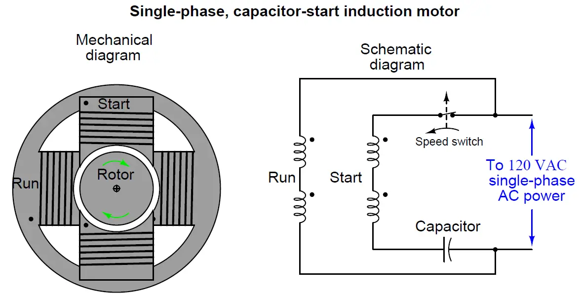
Since single-phase AC induction motors obviously exist, there must be a solution to this problem. In order to give the magnetic field within a single-phase stator assembly a definite rotation, we must artificially create a second phase within the motor itself. One common way to do this is to add a second set of stator windings offset from the first and energize those windings through a high voltage capacitor, which creates a leading phase shift in winding current. This phase shift creates an out-of-step magnetic field in the second winding set, providing a definite direction of rotation. Once the motor comes up to speed, this auxiliary winding may be disconnected by a speed-sending switch, since a spinning motor will happily run on single-phase AC. This is called a capacitor-start induction motor, and it is the design used for most single-phase AC induction motors requiring a high starting torque (e.g. pumps, shop grinders, drill presses, etc.):
One of the major principles to grasp about AC induction motors is that they must start as polyphase machines, although they may continue to run as single-phase machines.
A capacitor-start, single-phase electric motor is shown in the following photograph. My hand is touching the capacitor enclosure for the motor’s starting winding. The speed switch is internal to the motor and cannot be seen in this photograph:
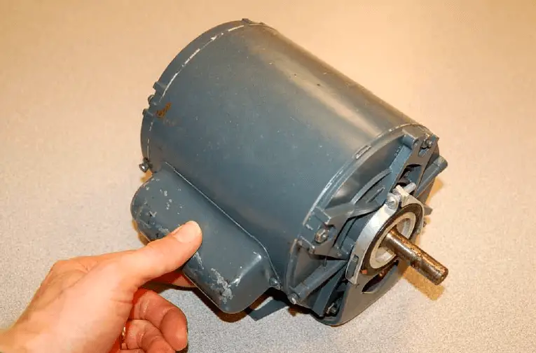
Capacitor-start motors are often designed in such a way that the starting winding draws much more current than the “run” winding, in order to provide a strong starting torque. This is important when the mechanical load being turned by the motor requires a great deal of torque to get moving, such as in the case of a reciprocating gas compressor or a fully-loaded conveyor belt. Due to this high current draw, starting windings are not rated for continuous duty, but rather must be de-energized shortly after starting the motor in order to avoid overheating.
Smaller AC motors, such as those used inside bench-top and rack-mount electronic equipment, use a completely different method for generating a rotating magnetic field from single-phase AC power. The following photograph shows one such motor, employing copper shading coils at the corners of the magnetic stator poles. The rotor has been removed, held by my fingers for inspection:
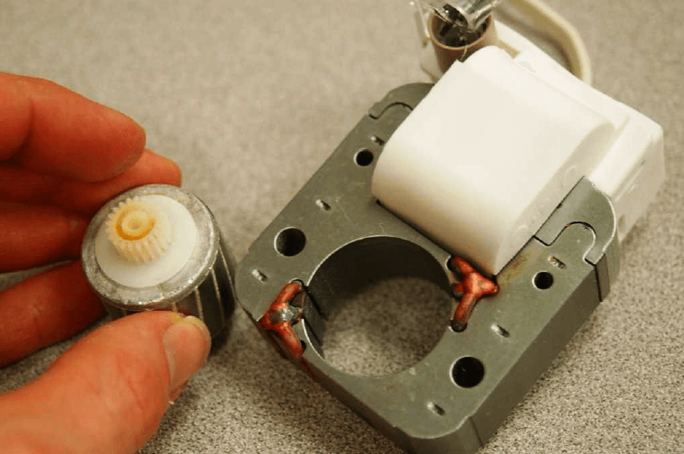
Instead of a capacitor creating a leading phase-shift for current through a special stator winding, this “shaded-pole” induction motor uses a pair of copper loops wrapped around the corners of the magnetic poles to produce a lagging phase shift in the magnetic field at those corners. The copper shading coils act as inductors, delaying the magnetic field through them by −90 deg, creating a secondary magnetic field that is out-of-step with the main magnetic field generated by the rest of the pole face. The out-of-step magnetic field together with the main magnetic field adjacent to it creates a definite direction of rotation
. An interesting experiment you can try yourself is to obtain one of these small shaded-pole AC motors and make it rotate by applying pulsed DC power to it, from a battery. Every time you connect the stator winding to the battery, the increasing magnetic flux will lead at the non-shaded pole faces and lag at the shaded pole faces. Every time you disconnect the stator winding from the battery, the decreasing magnetic flux will lead at the non-shaded pole faces and lag at the shaded pole faces. In either case, the shaded poles’ magnetic flux will lag behind that of the non-shaded poles, causing the rotor to rotate slightly in one definite direction.
The fact that all AC induction motors must start as polyphase machines even though they can run as single-phase machines means that an AC motor designed to run on three-phase power may actually continue to run if one or more of its phases are “lost” due to an open wire connection or blown fuse. The motor cannot deliver full-rated mechanical power in this condition, but if the mechanical load is light enough the motor will continue to spin even though it no longer has multiple phases powering it! A three-phase motor, however, cannot start from a stand-still on just one phase of AC power. The loss of phases to an AC induction motor is called single-phasing, and it may cause a great deal of trouble in an industrial facility. Three-phase electric motors that become “single phased” from a fault in one of the three-phase power lines will refuse to start. Those that were already running under heavy (high-torque) mechanical load will stall. In either case, the stopped motors will simply “hum” and draw large amounts of current.
Credits : by Tony R. Kuphaldt – under the terms and conditions of the Creative Commons Attribution 4.0 License