Inst ToolsInst ToolsInst Tools
  • Courses
  • Automation
    • PLC
    • Control System
    • Safety System
    • Communication
    • Fire & Gas System
  • Instrumentation
    • Design
    • Pressure
    • Temperature
    • Flow
    • Level
    • Vibration
    • Analyzer
    • Control Valve
    • Switch
    • Calibration
    • Erection & Commissioning
  • Interview
    • Instrumentation
    • Electrical
    • Electronics
    • Practical
  • Q&A
    • Instrumentation
    • Control System
    • Electrical
    • Electronics
    • Analog Electronics
    • Digital Electronics
    • Power Electronics
    • Microprocessor
  • Request
Search
  • Books
  • Software
  • Projects
  • Process
  • Tools
  • Basics
  • Formula
  • Power Plant
  • Root Cause Analysis
  • Electrical Basics
  • Animation
  • Standards
  • 4-20 mA Course
  • Siemens PLC Course
Reading: Ziegler-Nichols Closed Loop Tuning Procedure
Share
Font ResizerAa
Inst ToolsInst Tools
Font ResizerAa
  • Courses
  • Design
  • PLC
  • Interview
  • Control System
Search
  • Courses
  • Automation
    • PLC
    • Control System
    • Safety System
    • Communication
    • Fire & Gas System
  • Instrumentation
    • Design
    • Pressure
    • Temperature
    • Flow
    • Level
    • Vibration
    • Analyzer
    • Control Valve
    • Switch
    • Calibration
    • Erection & Commissioning
  • Interview
    • Instrumentation
    • Electrical
    • Electronics
    • Practical
  • Q&A
    • Instrumentation
    • Control System
    • Electrical
    • Electronics
    • Analog Electronics
    • Digital Electronics
    • Power Electronics
    • Microprocessor
  • Request
Follow US
All rights reserved. Reproduction in whole or in part without written permission is prohibited.
Inst Tools > Blog > Control Systems > Ziegler-Nichols Closed Loop Tuning Procedure

Ziegler-Nichols Closed Loop Tuning Procedure

Last updated: August 31, 2019 8:40 pm
Editorial Staff
Control Systems
No Comments
Share
3 Min Read
SHARE

The closed-loop, or “Ultimate” tuning method of Ziegler and Nichols was applied to this process.

Eliminating both integral and derivative control actions from the controller, and experimenting with different gain (proportional) values until self-sustaining oscillations of consistent amplitude (Note) were obtained, gave a gain value of 11, as shown in below figure.

Note : The astute observer will note the presence of some limiting (saturation) in the output waveform, as it attempts to go below zero percent.

Normally, this is unacceptable while determining the ultimate gain of a process, but here it was impossible to make the process oscillate at consistent amplitude without saturating on the output signal.

The gain of this process falls off quite a bit at the ultimate frequency, such that a high controller gain is necessary to sustain oscillations, causing the output waveform to have a large amplitude.

Ziegler-Nichols Closed Loop Tuning

Ziegler-Nichols Closed Loop Tuning Procedure

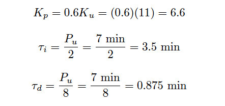
From the trend, we can see that the ultimate period (Pu) is approximately 7 minutes in length. Following the Ziegler-Nichols recommendations for PID tuning based on these process characteristics:

Ziegler-Nichols Closed Loop Tuning Formula

It should be immediately apparent that these tuning parameters will yield poor control. While the integral and derivative values are close to those predicted by the open-loop (Reaction Rate) method, the gain value calculated here is even larger than what was calculated before.

Since we know proportional action was excessive in the last tuning attempt, and this one recommends an even higher gain value, we can expect our next trial to oscillate even worse.

Applying the PID values of 6.6 (gain), 3.5 minutes per repeat (integral), and 0.875 minute (derivative) gave the following result in automatic mode:

Ziegler-Nichols Loop Tuning

This time the loop stability is a bit worse than with the PID values given by the Ziegler-Nichols open-loop tuning equations, owing mostly to the increased controller gain value of 6.6 (versus 4.5).

Proportional action is still the dominant mode of control here, as revealed by the minimal phase shift between PV and OUT waveforms (ignoring the 180 degrees of shift inherent to the controller’s reverse action).

In all fairness to the Ziegler-Nichols technique, the excessive controller gain value probably resulted more from the saturated output waveform than anything else. This led to more controller gain being necessary to sustain oscillations, leading to an inflated Kp value.

Don't Miss Our Updates
Be the first to get exclusive content straight to your email.
We promise not to spam you. You can unsubscribe at any time.
Invalid email address
You've successfully subscribed !

Continue Reading

Yokogawa DCS and SIS System Architecture
What is a Surge Protection Device? – Principle, Types, Advantages
IoT based Smart Boiler Control System with Cloud PLC and SCADA
Why Use a Current Loop?
Industrial Automation in the Mining Industry
Feedback Control Principle
Share This Article
Facebook Whatsapp Whatsapp LinkedIn Copy Link
Share
Leave a Comment

Leave a Reply Cancel reply

Your email address will not be published. Required fields are marked *

Stay Connected

128.3kFollowersLike
69.1kFollowersFollow
210kSubscribersSubscribe
38kFollowersFollow

Categories

Explore More

Types of Control Systems
DCS Controllers to Output Current Loops
What is Indicator ?
Difference between ON-OFF Controller and PID Controller
Cyber Security Multiple Choice Questions and Answers
Compressor Emergency Shutdown Root Cause Analysis
How to Configure a Smart Transmitter Using a HART Communicator?
Difference Between SCADA and HMI

Keep Learning

Design Logic Diagrams with Standard Formats for Process Control

Design Logic Diagrams with Standard Formats for Process Control

Transmitters 4-20mA Current Failure Alarm Limits

Transmitters 4-20mA Current Failure Alarm Limits

open vs closed loop

Open Loop and Closed Loop Animation

Siemens PCS 7

What is PCS 7?

How Valve Positioners act as Cascade Control Systems in a Loop?

How Valve Positioners act as Cascade Control Systems in a Loop?

Turbine-Compressor System Architecture

Turbine-Compressor System Architecture

Industrial Automation and Control

100+ Questions and Answers on Industrial Automation and Control

Cable Glands

Using of MCT instead of Cable Glands on the Cabinets

Learn More

How a Diode Works Animation

How a Gate Works ?

What is Oscilloscope

What is Cathode Ray oscilloscope ?

PLC Program for Automatic Parameter initialization

PLC Program for Automatic Parameter Initialization When Power UP

Power Systems Operation and Control Interview questions

Power Systems Operation and Control Interview questions

Input function blocks

FF Function Blocks

Pneumatic Valves Questions & Answers

Pneumatic Valves Questions & Answers

PLC Sequential Operation Example Program

PLC Sequential Operation Example Program

Reverse Bias Diode Working Animation

Forward Bias & Reverse Bias Diode Working Animation

Menu

  • About
  • Privacy Policy
  • Copyright

Quick Links

  • Learn PLC
  • Helping Hand
  • Part Time Job

YouTube Subscribe

Follow US
All rights reserved. Reproduction in whole or in part without written permission is prohibited.
Welcome Back!

Sign in to your account

Username or Email Address
Password

Lost your password?