Thermocouples (TCs) and resistance temperature detectors (RTDs) are the most widely used temperature sensors in automation and process control. They are found embedded in motors, valves, turbines, bearings, and a host of other devices. Most smart instruments such as flowmeters, pressure transmitters, and level transmitters also have an embedded temperature sensor-used to correct the primary measured variable or for process control.
Theories of operation
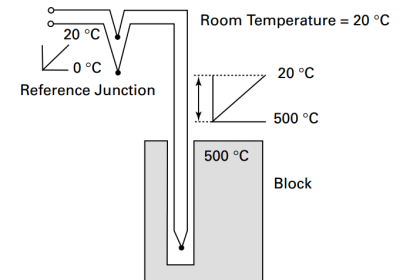
A thermocouple consists of two wires of dissimilar metals, joined at both ends-at the reference point outside the process (cold junction) and at a junction at the point of measurement (hot junction). The metals react differently to temperature changes and generate an electromotive force (EMF) voltage based on the temperature differential between the junctions (the Seebeck effect). A resistance temperature detector is based on the principle that electrical resistance in a wire increases with temperature.
In both cases, the sensor is wired to a transducer or signal conditioner that has been calibrated to accept the input voltage or resistance, calculate the correct temperature, and output it as a 4-20 mA, mV, or digital signal to an automation system.
The above is pretty basic, taught in every Instrumentation class. But it poses the first question to consider when choosing a sensor: How do you wire the sensor to the transducer, signal conditioner, or automation system? Such devices and systems, being electronic in nature, need to be mounted in a reasonably safe location, away from high temperatures.
TCs must be wired with thermocouple extension wire, which is the same as the wire used in the TC. For example, a Type K TC uses a wire of nickel-chromium connected at the sensing junction to a wire of nickel-alumel. Extension wire must be the same composition, that is, one nickel-chromium and one nickel-alumel wire. In general, longer runs of extension wire are discouraged, as the wires act as an antenna, making the measurement more susceptible to electromagnetic and radio frequency interference. Cost may also be an issue when dealing with long extension wires, especially ones with exotic materials (e.g., Type R TCs). In certain cases, a compensation cable made up of a less expensive material with similar EMF properties to the TC can be used.
RTDs, on the other hand, can be wired with standard cable for much longer distances; however, they are typically limited by issues related to self-heating errors. In both cases, the extension wiring must be shielded against electrical noise in the plant. Note that TC extension wire is more susceptible to noise than RTD cable.
Temperature Measuring Environments
Temperature sensing is often done in “unfriendly” environments, such as corrosive, oxidizing, or reducing atmospheres, often accompanied by severe vibration and electrical noise. When selecting an RTD or TC, the environment must be taken into account. If the process environment poses a high degree of risk of sensor failure, a thermowell made of a material that is suitable for the process environment should be considered.
Vibration-Wire-wound RTDs are most susceptible to vibration. Wire-wound RTDs can fail from mechanical stress in high-vibration applications and should not be used. Thin-film RTDs have a higher tolerance for vibration, but they are not as good as TCs, which have the highest resistance to vibration.
Electrical noise-As noted above, the extension wires for both RTDs and TCs are susceptible to electrical noise. In high-noise environments, extension wires should be sheathed, shielded, grounded, and kept as short as possible. An RTD is a better choice in high-noise environments.
Harsh environments-When dealing with a harsh environment, check to see if the RTD or TC sensor manufacturer offers protection against adverse conditions. Wire-wound RTDs in their protective casings are quite rugged and immune to most environmental problems. For additional protection, RTDs can be coated with perfluoroalkoxy (PFA) polytetrafluoroethylene for use in plating baths, highly pressurized systems, or similar applications. RTD extension wires are available with polyvinyl chloride, PFA, or fiberglass insulation for protection.
TCs, especially those with metal cases, are much more rugged than RTDs and better able to deal with corrosive or oxidizing atmospheres. When exposed TC junctions are used, special care must be taken in harsh environments.
TCs are classified by type, i.e., Types E, J, K, N, T, S, R, and B. Each type is suitable for a specific temperature range from -201°C to 1700°C, and the construction of each makes it suitable for use in various environments:
- Type E: suitable for vacuum, inert, mildly oxidizing, or reducing atmospheres
- Type J: may be used, exposed or unexposed, where there is a deficiency of free oxygen
- Type K: typically requires metal or ceramic protection
- Type N: resists oxidation where sulfur is present
- Type T: can be used in either oxidizing or reducing atmospheres
- Types S, R, B: should always be protected with a ceramic tube, a secondary tube of porcelain, and a silicon carbide or metal outer tube as conditions require
Major Considerations involved in selecting a TC or RTD
Measuring range: RTDs can measure temperatures up to 1000°C, but it can be difficult to get accurate measurements from an RTD at temperatures above 400°C. TCs can measure up to 1700°C. The generally accepted rule is: for temperatures below 850°C, use an RTD for accuracy; for temperatures above 850°C, use a TC. Industrial measurements typically are 200°C to 400°C, so an RTD may be the best choice in that range.
Response time: While both sensors respond quickly to temperature changes, TCs are faster. In certain cases, however, manufacturing processes allow for production of thin-film RTDs with greatly improved response times.
Dimensions: Both sensors are fairly small, at about 0.5 mm diameter. If space is an issue for mounting a sensor, check with the supplier for size and mounting options.
Vibration: In general, TCs are less susceptible to vibration than RTDs. However, in certain manufacturing processes thin-film RTDs can be produced that are capable of much greater vibration resistance than standard RTDs.
Self-heating: An RTD is made of very fine wires or very fine coatings, and requires a voltage from a power supply-TCs do not require power. Although the power required is only 1 mA to 10 mA, it can cause the platinum element in the RTD to “heat up,” thus affecting accuracy of the measurement. If long extension wires are used, more power may be needed to overcome resistance in the wires, thus increasing the self-heating problem.
Stability: The long-term stability of an RTD is very good, meaning that its readings will be repeatable and stable for a long time. TCs, on the other hand, tend to drift. The EMF produced by a TC can change over time because of oxidation, corrosion, and other changes in the metallurgical properties of the sensing elements. TC drift is irreversible, and some provision is needed to detect it, such as software or testing for loop resistance.
Accuracy: As a general rule, RTDs are more accurate than TCs. RTDs can produce accuracy of 0.1C, while TCs are typically accurate to only 1C.
Although not a technical issue, TCs are considerably less expensive than RTDs due primarily to lower production costs. Depending on the number of sensors needed for a particular application, this could be a major factor.
Careful selection of the right temperature sensing technology is essential to ensure the best performance, reliability, and cost effectiveness. Suppliers that sell both TCs and RTDs are often good sources of information when deciding which type of sensor to use.
Why choose RTD over Thermocouple ?
Better Accuracy & Repeatability
– RTD signal less susceptible to noise
– Better linearity
– RTD can be “matched” to transmitter (Interchangeability error eliminated)
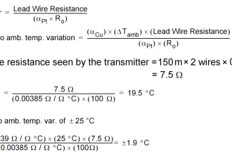
– CJC error inherent with T/C’s; RTD’s lead wire resistance errors can be eliminated
Better Stability
– T/C drift is erratic and unpredictable; RTD’s drift predictably
– T/C’s cannot be re-calibrated
Greater Flexibility
– Special extension wires not needed
– Don’t need to be careful with cold junctions
Why choose thermocouple over RTD ?
Applications for Higher Temperatures
• Above 1100°F
Lower Element Cost
• Cost is the same when considering temperature point performance requirements
Faster response time
• Insignificant compared to response time for T-Well and process
Perceived as more rugged
• Rosemount construction techniques produce extremely rugged RTD
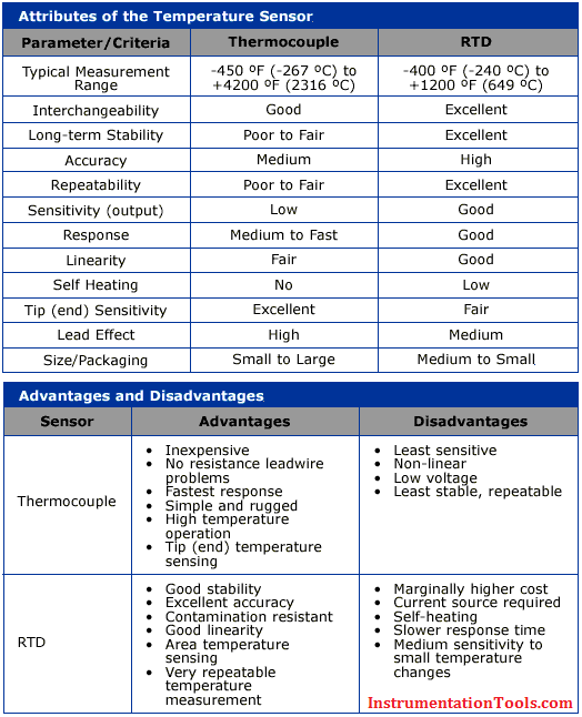
RTD vs Thermocouple Comparison Chart
Also Read: How to Test a Thermocouple


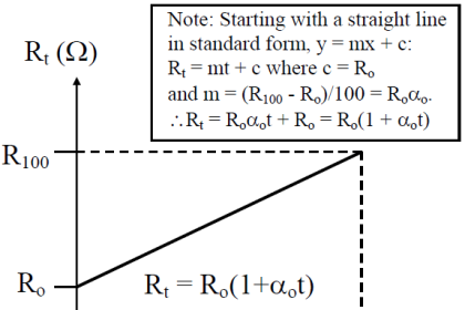


can you please tell me on the RTD chart. How much temperature is how much resistance?