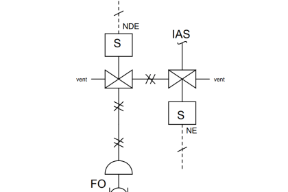
Control valves used in pneumatic and hydraulic fluid power systems often take the form of a spool mechanism, and the fluid power schematic symbols for these spool valves are quite unlike that of valve symbols in P&IDs and loop diagrams:
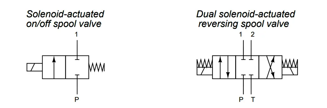
Explain what these spool valve symbols represent, and how they are to be interpreted. Also, comment on the construction of a spool valve.
Answer:
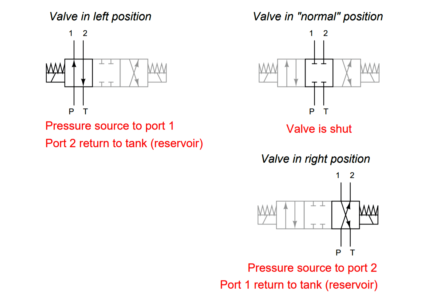
The symbols show each valve’s “normal” (unactuated) position. To understand what happens when the valve is actuated, you must visualize the boxes sliding over into alignment with the inlet/outlet pipes, like this:
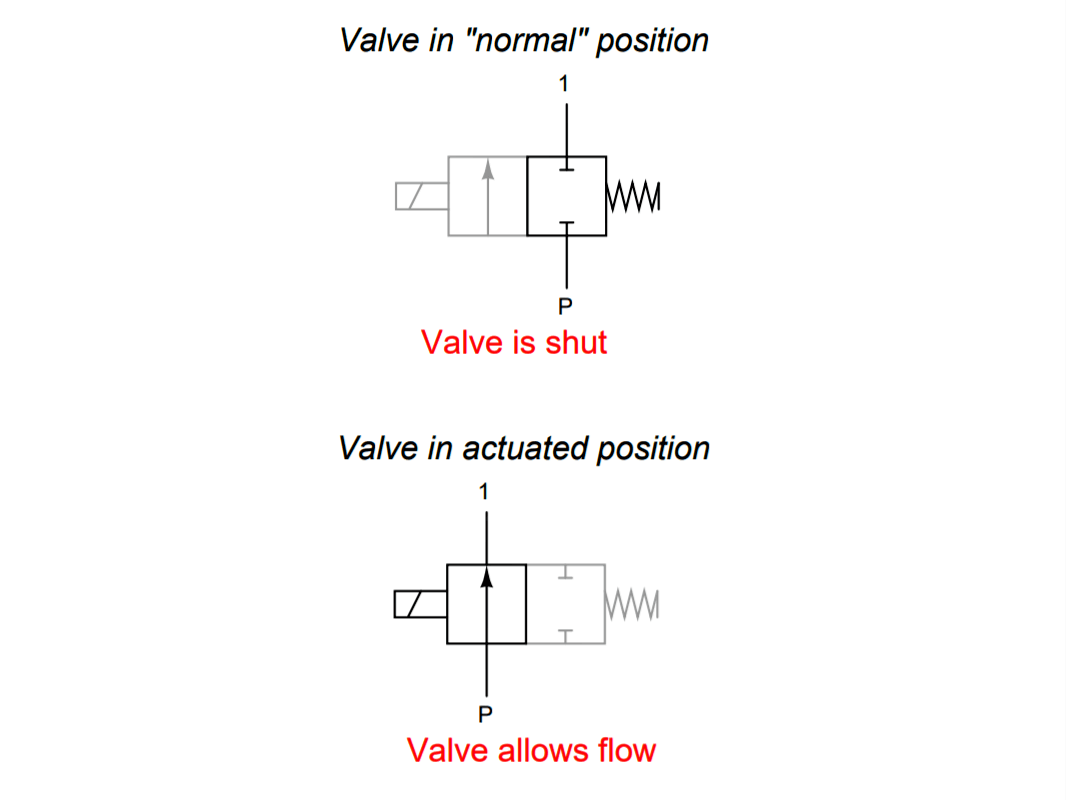
The same holds for the reversing valve, except that it has three positions:
Share your answers with us through the below comments section.
Read Next:
Credits: Tony R. Kuphaldt