Inst ToolsInst ToolsInst Tools
  • Courses
  • Videos
  • Q & A
    • Interview
      • Instrumentation
      • Electronics
      • Electrical
      • Practical Questions
    • MCQ
      • Instrumentation MCQ
      • Electrical MCQ
      • Electronics MCQ
      • Control Systems MCQ
      • Analog Electronics MCQ
      • Digital Electronics MCQ
      • Power Electronics MCQ
      • Microprocessor MCQ
      • Multiple Choice Questions
  • EE
    • Electronics
      • Electronics Q & A
      • Electronic Basics
      • Electronic Devices & Circuits
      • Electronics Animation
      • Digital Electronics
    • Electrical
      • Electrical Basics
      • Electrical Q & A
      • Power Electronics
      • Electrical Machines
      • Electrical Animation
      • Power Systems
      • Switchgear & Protection
      • Transmission & Distribution
  • Measure
    • Control Valves
    • Calibration
    • Temperature
    • Pressure
    • Flow
    • Level
    • Analyzers
    • Switches
    • Vibration
    • Solenoid Valve
  • Control
    • PLC Tutorials
    • Control Systems
    • Safety Instrumented System (SIS)
    • Communication
    • Fire & Gas System
  • More
    • Design
    • Tools
    • Animation
    • Basics
    • Formulas
    • Standards
    • TextBooks
    • Common
    • Software
    • Excel Tools
    • Erection & Commissioning
    • Process Fundamentals
    • Videos
    • Books
Search
All rights reserved. Reproduction in whole or in part without written permission is prohibited.
Reading: What is HIPPS System in Oil and Gas?
Share
Notification Show More
Font ResizerAa
Inst ToolsInst Tools
Font ResizerAa
  • Courses
  • PLC Tutorials
  • Control Systems
Search
  • Courses
  • Videos
  • Q & A
    • Interview
    • MCQ
  • EE
    • Electronics
    • Electrical
  • Measure
    • Control Valves
    • Calibration
    • Temperature
    • Pressure
    • Flow
    • Level
    • Analyzers
    • Switches
    • Vibration
    • Solenoid Valve
  • Control
    • PLC Tutorials
    • Control Systems
    • Safety Instrumented System (SIS)
    • Communication
    • Fire & Gas System
  • More
    • Design
    • Tools
    • Animation
    • Basics
    • Formulas
    • Standards
    • TextBooks
    • Common
    • Software
    • Excel Tools
    • Erection & Commissioning
    • Process Fundamentals
    • Videos
    • Books
Follow US
All rights reserved. Reproduction in whole or in part without written permission is prohibited.
Inst Tools > Blog > Safety Instrumented System (SIS) > What is HIPPS System in Oil and Gas?

What is HIPPS System in Oil and Gas?

Last updated: May 9, 2022 10:59 am
Editorial Staff
Safety Instrumented System (SIS)
No Comments
Share
3 Min Read
SHARE

HIPS (High Integrity Protection System), is also sometimes referred to as High Integrity Pressure-Protection System (HIPPS).

Contents
When do we need HIPPS?High Integrity Pressure-Protection System OverviewBasic PrincipleHIPPS WorkflowHIPPS DocumentationHIPPS Registration

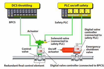
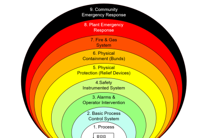
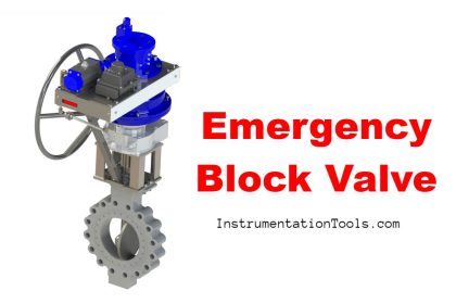
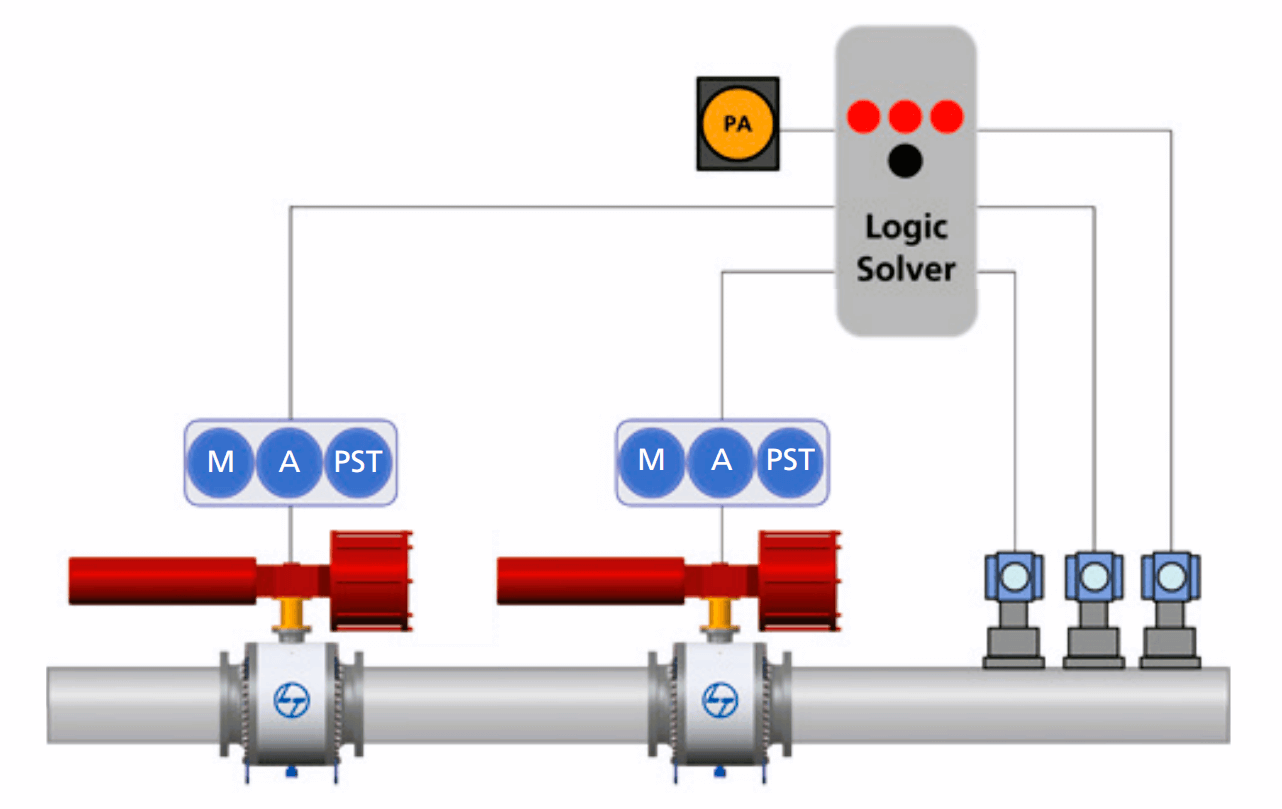
HIPPS is a collection of independent protection layers to mitigate an overpressure scenario. It is a combination of mechanical protection like Relief devices together with an automated system like Shutoff valves with associated instruments.

When do we need HIPPS?

HIPPS are considered if relief device vents are not acceptable due to safety or environmental concerns.

If the maintainability of the vent is excessively expensive

If the conventional systems are not adequate

If the relief system may create a greater hazard.

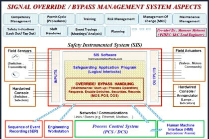
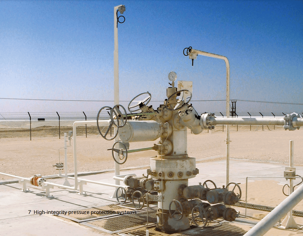
HIPPS (High Integrity Pressure-Protection System) is a protection method to control risk in case of excessive pressure by considering Safety Instrumented Systems (SIS) and other Independent Protection Layers.   

What is HIPPS System in Oil and Gas
Image Courtesy: L&T Valves

High Integrity Pressure-Protection System Overview

  • HIPPS is used to mitigate a specific relief scenario.  HIPPS is not intended to completely eliminate a relief valve. 
  • Minimum SIL-1 requirement for HIPPS: LOPA determines actual SIL.
  • When the size of the relief device installation is huge or the area is not comfortable to do the installation HIPPS comes into the picture.

Basic Principle

Install a mechanical, self-actuated, relief device for an overpressure scenario shall be the preferred choice as these devices respond to overpressure, regardless of the cause. As an additional protection use instrumented protection layers (there are limitations of common cause failures).

Conventional relief devices have been proven available to perform a specified protective function on demand for over a hundred years. These self-actuating mechanical systems are usually independent of other Independent Protection Layers.

The technology (other than sizing) is simple as compared to most instrumented systems and usually easy (though not always inexpensive) to maintain.

HIPPS Workflow

Steps:

  1. Determine if HIPPS is a better alternative.
    1. Must meet defined criteria for applying HIPPS.
    1. Relief designer usually discovers the need for HIPPS.
  2. Perform LOPA for Overpressure Scenario
    1. Credit all independent layers of protection (IPL’s).
    1. Determine required SIL for SIS (Minimum SIL-1).
  3. Design & installation per SIS/LOPA Work Process.
    1. All SIS/LOPA work process requirements apply.
    1. Track & audit HIPPS within SIS/LOPA.
    1. All SIS’s, including HIPPS, share the same integrity management processes.
  4. Final Review and Approval
    1. End user review and approval.
    1. Documentation archived – to be documented in Mechanical equipment integrity files.
High Integrity Pressure-Protection System Image
Image Courtesy: Yokogawa

HIPPS Documentation

HIPPS shall be noted on the P&ID and Safety Instrumented System Loop Documentation Form. A registration form shall be completed for each HIPPS. 

HIPPS Registration

HIPPS systems are registered in the pressure relief registry.

  • Identify the LOPA scenario number & describe the scenario.
    • Identify SIF numbers & describe their function.
    • Describe the relief scenario mitigated by the HIPPS.
    • Document the reason for using HIPPS.
    • Reference associated conventional relief device, when applicable.
    • Authorized approvals viz. Design lead, Production leader, etc.
Don't Miss Our Updates
Be the first to get exclusive content straight to your email.
We promise not to spam you. You can unsubscribe at any time.
Invalid email address
You've successfully subscribed !

Recommended Articles

Safety Instrumented System Module Failure
Rupture disks
Understanding High Integrity Pressure Protection Systems (HIPPS)
Understanding Safety Integrity Level IEC 61511
Control Valve Failure Rate Calculation
Understanding Emergency Shutdown Button Installation (ESD)
Share This Article
Facebook Whatsapp Whatsapp LinkedIn Copy Link
Share
Leave a Comment

Leave a Reply Cancel reply

Your email address will not be published. Required fields are marked *

Stay Connected

128.3kFollowersLike
69.1kFollowersFollow
208kSubscribersSubscribe
38kFollowersFollow

Categories

Recent Comments

  • William Snyder on Top Non-PLC Certification Courses for Automation Professionals
  • Kamli on Top Free PLC Software
  • Guifty Shimica on Top Non-PLC Certification Courses for Automation Professionals
  • Guifty Shimica on Top Non-PLC Certification Courses for Automation Professionals

Related Articles

Emergency Shutdown Valve

Emergency Shutdown Valve : Advantages

Reliability of a Control System

Reliability of a Control System

Safety Instrumented System Interview Questions Answers

Safety Instrumented System Interview Questions and Answers

Project Management of Safety Instrumented System

Project Management of Safety Instrumented System (SIS)

Emergency Shutdown System Philosophy

Shutdown Philosophy

safety PLC programming

SIS Logic Solver

Emergency ShutDown Valve Working Principle

ESDV : How it Works ?

SIS PFD - Safety Instrumented System

SIS PFD – Safety Instrumented System

More Articles

Temperature Balance System Objective Questions

Temperature Balance System Objective Questions

Thermowell Design Guidelines

Globe Valve Parts

What is Globe Valve ?

Direct Mounting of Diaphragm Seals Level Transmitter

What are the Mounting Techniques of Diaphragm Seals?

DP type Flow Transmitter Preventive Maintenance

Troubleshooting DP type Transmitter Common Problems

Pressure Transmitters Installation Factors

Pressure Transmitters Installation Tips

Coriolis mass flowmeter Density Measurement

How Coriolis Mass Flow Meter Measure Density?

Range Finders

Range Finders – Ultrasonic, Light, & Global Positioning Systems

Follow US
All rights reserved. Reproduction in whole or in part without written permission is prohibited.
Welcome Back!

Sign in to your account

Username or Email Address
Password

Lost your password?