Inst ToolsInst ToolsInst Tools
  • Courses
  • Automation
    • PLC
    • Control System
    • Safety System
    • Communication
    • Fire & Gas System
  • Instrumentation
    • Design
    • Pressure
    • Temperature
    • Flow
    • Level
    • Vibration
    • Analyzer
    • Control Valve
    • Switch
    • Calibration
    • Erection & Commissioning
  • Interview
    • Instrumentation
    • Electrical
    • Electronics
    • Practical
  • Q&A
    • Instrumentation
    • Control System
    • Electrical
    • Electronics
    • Analog Electronics
    • Digital Electronics
    • Power Electronics
    • Microprocessor
  • Request
Search
  • Books
  • Software
  • Projects
  • Process
  • Tools
  • Basics
  • Formula
  • Power Plant
  • Root Cause Analysis
  • Electrical Basics
  • Animation
  • Standards
  • 4-20 mA Course
  • Siemens PLC Course
Reading: What is a Control Loop ?
Share
Font ResizerAa
Inst ToolsInst Tools
Font ResizerAa
  • Courses
  • Design
  • PLC
  • Interview
  • Control System
Search
  • Courses
  • Automation
    • PLC
    • Control System
    • Safety System
    • Communication
    • Fire & Gas System
  • Instrumentation
    • Design
    • Pressure
    • Temperature
    • Flow
    • Level
    • Vibration
    • Analyzer
    • Control Valve
    • Switch
    • Calibration
    • Erection & Commissioning
  • Interview
    • Instrumentation
    • Electrical
    • Electronics
    • Practical
  • Q&A
    • Instrumentation
    • Control System
    • Electrical
    • Electronics
    • Analog Electronics
    • Digital Electronics
    • Power Electronics
    • Microprocessor
  • Request
Follow US
All rights reserved. Reproduction in whole or in part without written permission is prohibited.
Inst Tools > Blog > Control Systems > What is a Control Loop ?

What is a Control Loop ?

Last updated: July 8, 2020 10:06 pm
Editorial Staff
Control Systems Instrumentation Design Process
No Comments
Share
2 Min Read
SHARE

A control loop is a process management system designed to maintain a process variable at a desired set point.

Contents
Control LoopThe Control Loop Steps :Principle :Understanding a Control Loop :

Each step in the loop works in conjunction with the others to manage the system. Once the set point has been established, the control loop operates using a four-step process.

Control Loop

Control Loop

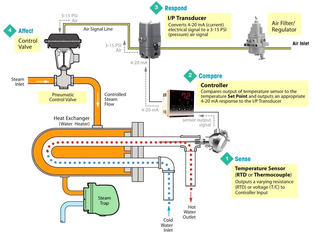
Image Credits : watsonmcdaniel.com

The Control Loop Steps :

Sense :

Measure the current condition of the process using a sensor, which can be a thermocouple or RTD transmitter.

Compare :

Evaluate the measurement of the current condition against the set point using an electronic PID controller.

Respond :

Reacts to any error that may exist between the measured temperature value and the temperature set point by generating a corrective pneumatic signal.

Affect :

Actuate the control valve that will produce a change in the process variable.

The loop continually cycles through the steps, affecting the process variable (water temperature) in order to maintain the desired temperature set point.

Principle :

An electronic sensor (thermocouple, RTD or transmitter) installed at the measurement location continuously sends an input signal to the controller.

At set intervals, the controller compares this signal to a predefined set point. If the input signal deviates from the set point, the controller sends a corrective electric output signal to the control element.

This electric signal must be converted to a pneumatic signal when used with an air operated valve.

Using a I/P Transducer, which converts a 4 to 20 mA electric signal to a 3 to 15 PSI air signal and sends the respective air supply to the Control Valve Positioner.

The valve positioner adjusts the control valve stem position and regulates the flow through the control valve, accordingly the temperature controls. This loop repeats until controller achieves setpoint.

Understanding a Control Loop :

Heat Exchanger Control Loop Example

Process Control Loop

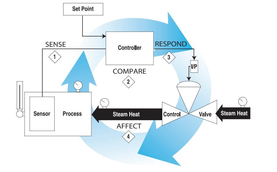
Image Credits : trerice.com

Don't Miss Our Updates
Be the first to get exclusive content straight to your email.
We promise not to spam you. You can unsubscribe at any time.
Invalid email address
You've successfully subscribed !

Continue Reading

How Modbus is used in Industrial Networks?
How to Select a Conductivity Meter
Steam Tracing
Industrial Automation System Architecture Reference Model
What is ERP in Industrial Automation? – Enterprise Resource Planning
Difference Between PNP and NPN Sensors
Share This Article
Facebook Whatsapp Whatsapp LinkedIn Copy Link
Share
Leave a Comment

Leave a Reply Cancel reply

Your email address will not be published. Required fields are marked *

Stay Connected

128.3kFollowersLike
69.1kFollowersFollow
210kSubscribersSubscribe
38kFollowersFollow

Categories

Explore More

Why 4-20 mA Current Signal is used instead of Voltage Signal?
Heuristic PID Tuning Method
Problem in Water Level Control System
What is DeviceNet?
What is PV Tracking ?
Types of Cathodic Protection for Pipeline Protection
Configuration of Control Valve in Studio 5000
4-20mA Loop Power Supply Questions and Answers

Keep Learning

interview-questions-and-answers-on-natural-gas

Oil and Gas Interview Questions Answers

Heat Exchanger Outlet Temperature Control

Heat Exchanger Temperature Control

annunciator-alarm-simulator

Alarm Simulator for Annunciator Logic

Location of Measurement Displays

Location of Measurement Displays

4 TO 20 MA ANALOG CURRENT SIGNALS

Basics of 4 to 20 mA analog Signals

Pressure Gauge Design

How to Select a Pressure Gauge

Load Cell Design

Load Cell Design

Steam Turbine Driven Centrifugal Compressors Leak due to Broken Instrument

Steam Turbine Driven Centrifugal Compressors Leak due to Broken Instrument

Learn More

Electrical Machines Questions and Answers

Synchronous Machines Distributed Winding Quiz

Loop Diagram

15 Loop Diagram Questions

Reactive Power Sources and Sinks in Power System

Reactive Power Sources and Sinks in Power System

transformers-questions-answers-part-1

Transformers Questions & Answers Part-1

Valve Positioner Torn apart

Pipeline Shakes Torn apart Valve Positioners

Analog Electronics Objective Questions

Analog Electronics Objective Questions – Set 4

RF-Capacitance Level Switch Principle

RF Capacitance Level Switch Working Principle

HART Layers vs OSI Layers

HART Communication Tutorial Part 3

Menu

  • About
  • Privacy Policy
  • Copyright

Quick Links

  • Learn PLC
  • Helping Hand
  • Part Time Job

YouTube Subscribe

Follow US
All rights reserved. Reproduction in whole or in part without written permission is prohibited.
Welcome Back!

Sign in to your account

Username or Email Address
Password

Lost your password?