In the world of industrial automation, a variable frequency drive (VFD) is a motor controller that changes the frequency and voltage of an electric motor in order to control the speed of the motor.
Controlling motor speed has been one of the main requirements in process control industries.
Other names for a VFD are:
An electronic speed regulator is made up of circuits that incorporate power transistors such as Insulated Gate Bipolar transistors (IGBTs) or thyristors.
The basic operating principle is to transform industrial frequency electrical energy into variable frequency electrical energy.
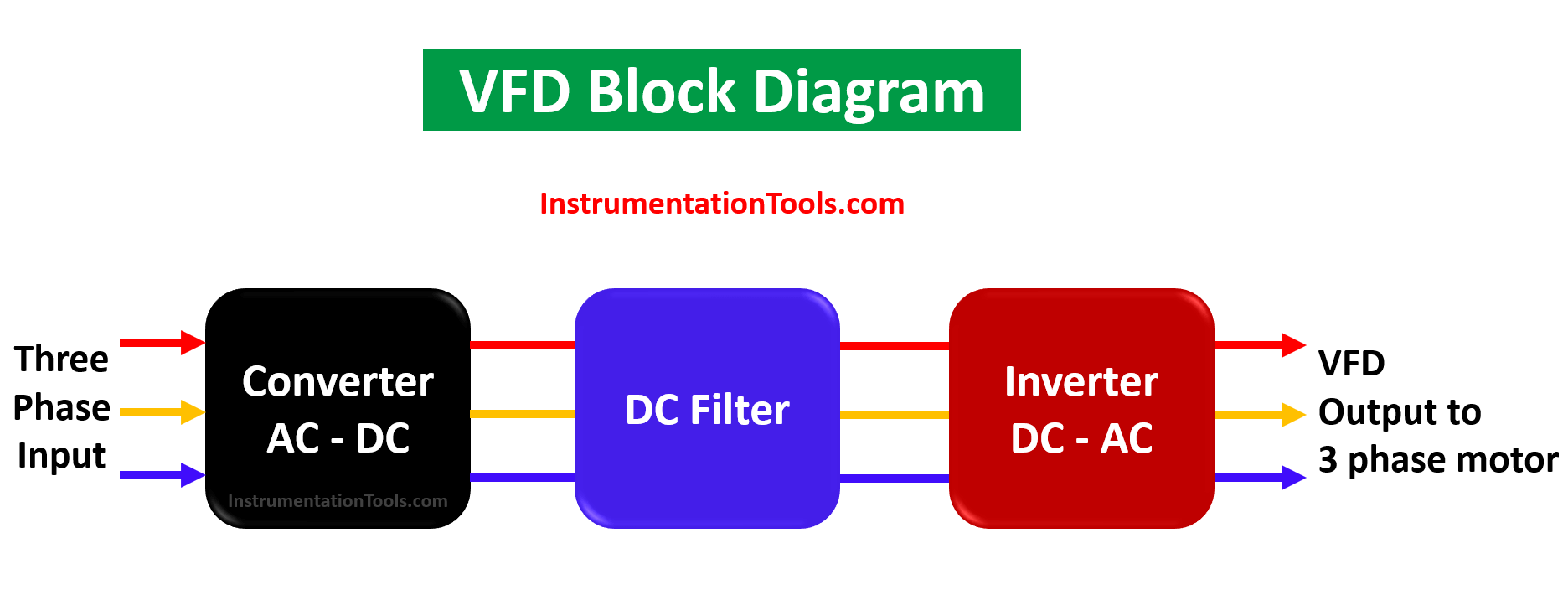
The frequency variation is achieved by two stages in series.
The entire frequency converter assembly is called an inverter.
Variable frequency drives are systems that are located between the electrical power supply and the electric motors.
VFDs are used to regulate the speed of motors by varying the alternating current (AC).
The frequency converter also has the ability to control the ramp-up and ramp-down of the motor when starting or stopping, respectively, even though the drive controls the frequency and voltage of the motor for regulating its speed.
Also Read: VFD Working Principle
By regulating the frequency of the electricity received by the motor, the frequency inverter manages to offer this motor the demanded electricity. Thus avoiding energy loss, or what is the same, optimizing consumption.
In an AC motor, the mechanical speed of the rotor is related to the frequency of the currents in the stator. It is possible to control the speed of the rotor by controlling the frequency of the current to the stator.
There is a direct relationship between the control of the frequency of the current at the stator and the mechanical speed, to fix the corresponding stator frequency.
It is on this principle that the operation of the VFD is based – for controlling a mechanical rotation speed by controlling the frequency of the stator current.
We know that any motor connected to the electrical power network has a certain torque and certain speed. In the event that they do not meet the requirements of a specific system, we can count on a frequency variation to adjust it to our needs.
Also Read: VFD and PLC Programming
In short, it is about controlling the speed of the motor. Frequency converters “convert”
(hence their name) the alternating current (AC) converted into direct current (DC).
The beginning steps in the process are carried out by an essential part of the drive, called the rectifier. Afterward, the drive’s capacitors take care of the next phase. The capacitors are charged with the direct current transformed by the rectifier and smooth the waveform of the resulting electrical current.
Finally, the last stage is that of the inverter, which converts the direct current into alternating current, again. This is how the motor actually receives the supply adjusted to the needs of adequate frequency and voltage.
Despite the wide variety of VFD models and manufacturers, the basic selection process is the same.
The following are the details that will help in choosing the right VFD.
The variable speed drives have several advantages:
Some disadvantages of VFD drives are mentioned below.
If you liked this article, then please subscribe to our YouTube Channel for Instrumentation, Electrical, PLC, and SCADA video tutorials.
You can also follow us on Facebook and Twitter to receive daily updates.
Read Next:
Learn an example PLC program to control a pump based on level sensors using ladder…
In the PLC timer application for security camera recording, when motion is detected then camera…
In this example, we will learn batch mixing with PLC ladder logic program using timer…
This PLC example on manufacturing line assembly is an intermediate-level PLC program prepared for the…
In this article, you will learn the PLC programming example with pushbutton and motor control…
This article teaches how to convert Boolean logic to PLC programming ladder logic with the…
