Inst ToolsInst ToolsInst Tools
  • Courses
  • Automation
    • PLC
    • Control System
    • Safety System
    • Communication
    • Fire & Gas System
  • Instrumentation
    • Design
    • Pressure
    • Temperature
    • Flow
    • Level
    • Vibration
    • Analyzer
    • Control Valve
    • Switch
    • Calibration
    • Erection & Commissioning
  • Interview
    • Instrumentation
    • Electrical
    • Electronics
    • Practical
  • Q&A
    • Instrumentation
    • Control System
    • Electrical
    • Electronics
    • Analog Electronics
    • Digital Electronics
    • Power Electronics
    • Microprocessor
  • Request
Search
  • Books
  • Software
  • Projects
  • Process
  • Tools
  • Basics
  • Formula
  • Power Plant
  • Root Cause Analysis
  • Electrical Basics
  • Animation
  • Standards
  • 4-20 mA Course
  • Siemens PLC Course
Reading: What is a Clamp Meter?
Share
Font ResizerAa
Inst ToolsInst Tools
Font ResizerAa
  • Courses
  • Design
  • PLC
  • Interview
  • Control System
Search
  • Courses
  • Automation
    • PLC
    • Control System
    • Safety System
    • Communication
    • Fire & Gas System
  • Instrumentation
    • Design
    • Pressure
    • Temperature
    • Flow
    • Level
    • Vibration
    • Analyzer
    • Control Valve
    • Switch
    • Calibration
    • Erection & Commissioning
  • Interview
    • Instrumentation
    • Electrical
    • Electronics
    • Practical
  • Q&A
    • Instrumentation
    • Control System
    • Electrical
    • Electronics
    • Analog Electronics
    • Digital Electronics
    • Power Electronics
    • Microprocessor
  • Request
Follow US
All rights reserved. Reproduction in whole or in part without written permission is prohibited.
Inst Tools > Blog > Electronic Basics > What is a Clamp Meter?

What is a Clamp Meter?

Last updated: April 27, 2017 4:20 am
Editorial Staff
Electronic Basics
1 Comment
Share
4 Min Read
SHARE

A clamp meter is an electrical test tool that combines a basic digital multimeter with a current sensor.

Clamps measure current. Probes measure voltage. Having a hinged jaw integrated into an electrical meter allows technicians to clamp the jaws around a wire, cable or other conductor at any point in an electrical system, then measure current in that circuit without disconnecting/deenergizing it.

Beneath their plastic moldings, hard jaws consist of ferrite iron and are engineered to detect, concentrate and measure the magnetic field being generated by current as it flows through a conductor.

The diagram above identifies basic functions are:

Clamp Meter

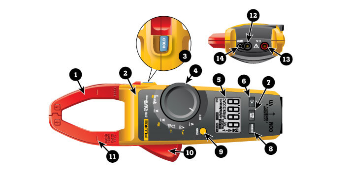
  1. Current-sensing jaw.
  2. Tactile barrier (to protect fingers from shocks).
  3. Hold button: Freezes the display reading. Reading is released when button is pushed a second time.
  4. Dial (aka rotary switch).
  5. Display.
  6. Backlight button.
  7. Min Max button: On first push, display shows maximum input. On subsequent pushes, minimum and average inputs are shown. Works in current, voltage and frequency modes.
  8. Inrush current button.
  9. Zero button (yellow): Removes dc offset from dc current measurements. Also serves as dial’s shift button to select yellow functions scattered around the dial.
  10. Jaw release lever.
  11. Alignment marks: To meet accuracy specifications, a conductor must be aligned with these marks.
  12. Common input jack.
  13. Volts/ohm input jack.
  14. Input for flexible current probe.

Originally created as a single-purpose test tool, modern clamp meters offer more measurement functions, greater accuracy and in some cases specialized measurement features. Today’s clamp meters include most of the basic functions of a digital multimeter (DMM), such as the ability to measure voltage, continuity and resistance.

Clamp meters have become popular tools primarily for two reasons:

  • Safety. Clamp meters allow electricians to bypass the old-school method of cutting into a wire and inserting a meter’s test leads into the circuit to take an in-line current measurement. The jaws of a clamp meter do not need to touch a conductor during a measurement.
  • Convenience. During a measurement, it is not necessary to shut off the circuit carrying current—a big boost in efficiency.

Clamp meters are preferred for measuring high levels of current. DMMs cannot measure 10 A of current for more than 30 seconds without risking damage to the meter.

Clamp meters offer a minimum current range of 0 A to 100 A. Many models have a range up to 600 A. Others go up to 999 A or 1400 A, and some plug-in clamp accessories such as the iFlex® can measure as high as 2500 A.

Clamp meters are used on industrial equipment, industrial controls, residential/commercial/industrial electrical systems, and commercial/industrial HVAC. They are primarily used for:

  • Service: To repair existing systems on an as-needed basis.
  • Installation: To troubleshoot installation problems, perform final circuit tests, and supervise apprentice electricians while installing electrical equipment.
  • Maintenance: To perform scheduled and preventative maintenance as well as system troubleshooting.

Three types of clamp meters exist:

  • Current transformer clamp meters: measure only alternating current (ac).
  • Hall Effect clamp meters: measure both alternating current and direct current (ac and dc).
  • Flexible clamp meters: employ a Rogowski coil; measure ac only; good for measuring in tight spaces.

While different, they share the same fundamental methodology when making measurements: A conductor is passed through a probe (either the hard jaws built into a clamp meter, or the flexible coil of a clamp accessory), and the vector sum of the currents flowing through the conductor is calculated by the meter.

Source : Fluke

Don't Miss Our Updates
Be the first to get exclusive content straight to your email.
We promise not to spam you. You can unsubscribe at any time.
Invalid email address
You've successfully subscribed !

Continue Reading

How to Measure Duty Cycle using Multimeter
What is an Inductor? – Types of Inductors
Things to Know When Measuring Current
Types of Potentiometers – What is a Potentiometer? – Applications
Difference Between LDR and Photodiode
How to Use SMD Components in Electronic Circuits?
Share This Article
Facebook Whatsapp Whatsapp LinkedIn Copy Link
Share
1 Comment
  • Nikhil Kulkarni says:
    May 16, 2016 at 9:37 am

    Good explanation.

    Reply

Leave a Reply Cancel reply

Your email address will not be published. Required fields are marked *

Stay Connected

128.3kFollowersLike
69.1kFollowersFollow
210kSubscribersSubscribe
38kFollowersFollow

Categories

Explore More

Testing a Transistor with a Digital Multimeter
Difference Between LED and LCD
Definition of Accuracy, Precision, Resolution, Range
Difference Between Electrical and Electronic Devices
How to Identify the Transistor Terminals
Difference Between Clamp Meters and Multimeters
How to Test Diodes Using Multimeter
What is Cathode Ray oscilloscope ?

Keep Learning

Factors Affecting Inductance

Factors Affecting Inductance

Difference between Analog Signal and Digital Signal

What are Analog and Digital Signals? Differences, Examples

Measure AC Voltage using Multimeter

How to Measure AC Voltage using Multimeter

Continuity Testing using Multimeter

How to do Continuity Testing using Multimeter

100 Electronics and Electrical Projects for Engineering Students

100 Electronics and Electrical Projects for Engineering Students

Seven Segment LED Display

Difference Between Common Cathode and Common Anode 7 Segment LED Display?

Top 100 555 Timer Projects for Engineering Students

Top 555 Timer Projects for Engineering Students

Difference of Energy Gap

Difference between Intrinsic and Extrinsic Semiconductors

Learn More

Identify Instrumentation Terms in Water Supply System

Identify Instrumentation Terms in Water Supply System

Digital Logic Gates TruthTables

Logic Gates

Electric Stress Control in Cables, Joints and Terminations

Electric Stress Control in Cables, Joints, and Terminations

Partial Discharge in Power Lines and its Detection through Sensors

Partial Discharge in Power Lines and its Detection through Sensors

Two Wire Transmitter Working Principle

Basics of Two, Three & Four Wire Transmitters

How to Test a Motor using Megger

How to Test a Motor using Megger?

Differential Pressure Gauge Principle

Piston Type Differential Pressure Gauge Principle

PLC Multiple Choice Questions

PLC Multiple Choice Questions

Menu

  • About
  • Privacy Policy
  • Copyright

Quick Links

  • Learn PLC
  • Helping Hand
  • Part Time Job

YouTube Subscribe

Follow US
All rights reserved. Reproduction in whole or in part without written permission is prohibited.
Welcome Back!

Sign in to your account

Username or Email Address
Password

Lost your password?