Inst ToolsInst ToolsInst Tools
  • Courses
  • Automation
    • PLC
    • Control System
    • Safety System
    • Communication
    • Fire & Gas System
  • Instrumentation
    • Design
    • Pressure
    • Temperature
    • Flow
    • Level
    • Vibration
    • Analyzer
    • Control Valve
    • Switch
    • Calibration
    • Erection & Commissioning
  • Interview
    • Instrumentation
    • Electrical
    • Electronics
    • Practical
  • Q&A
    • Instrumentation
    • Control System
    • Electrical
    • Electronics
    • Analog Electronics
    • Digital Electronics
    • Power Electronics
    • Microprocessor
  • Request
Search
  • Books
  • Software
  • Projects
  • Process
  • Tools
  • Basics
  • Formula
  • Power Plant
  • Root Cause Analysis
  • Electrical Basics
  • Animation
  • Standards
  • 4-20 mA Course
  • Siemens PLC Course
Reading: What is a Wave Trap? – Power Line Carrier Communication
Share
Font ResizerAa
Inst ToolsInst Tools
Font ResizerAa
  • Courses
  • Design
  • PLC
  • Interview
  • Control System
Search
  • Courses
  • Automation
    • PLC
    • Control System
    • Safety System
    • Communication
    • Fire & Gas System
  • Instrumentation
    • Design
    • Pressure
    • Temperature
    • Flow
    • Level
    • Vibration
    • Analyzer
    • Control Valve
    • Switch
    • Calibration
    • Erection & Commissioning
  • Interview
    • Instrumentation
    • Electrical
    • Electronics
    • Practical
  • Q&A
    • Instrumentation
    • Control System
    • Electrical
    • Electronics
    • Analog Electronics
    • Digital Electronics
    • Power Electronics
    • Microprocessor
  • Request
Follow US
All rights reserved. Reproduction in whole or in part without written permission is prohibited.
Inst Tools > Blog > Electrical Basics > What is a Wave Trap? – Power Line Carrier Communication

What is a Wave Trap? – Power Line Carrier Communication

A wave trap is a device that is used to block communication signals from passing through it and only allows power signals to pass through it.

Last updated: January 28, 2023 8:30 pm
Viral Nagda
Electrical Basics
No Comments
Share
6 Min Read
SHARE

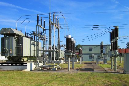
We all know that power transmission lines are used to carry electrical power from one end to another. It is majorly carried out with the help of substations.

Contents
Power Line Carrier Communication (PLCC)Wave TrapWave Trap Connection

But, do you know that these power lines can also carry communication signals apart from standard power signals? So, related to this concept, there is one important device used in electrical substations for helping this concept work properly. This device is called a wave or line trap.

In this post, we will learn the concept related to a wave trap.

Power Line Carrier Communication (PLCC)

First of all, let us, first of all, understand how we can transfer power and data communication in a single cable. This technique is called Power Line Carrier Communication (PLCC).

When you are transmitting and receiving data through power lines, you will require PLCC transmitters and receivers at both ends to communicate properly.

Basically, the normal data voltage is modulated to a very high frequency and superimposed on a standard low power frequency (in India, it is standard 50 Hz).

Due to superimposing, two separate frequencies can travel at the same time in the same line. When it is received at the PLCC receiver, the data frequency is separated from the power frequency and we can thus use the final received output then. Due to this, we can use both frequencies in the same line.

Wave Trap

Now, let us see a major issue related to this PLCC technique. As we saw, both signals are at different frequencies. The standard power frequency can be a maximum of 60 Hz, but the communication frequency can go up to a maximum of 800 kHz. The equipment used in a substation-like transformer is sensitive and designed only for the operation of up to 60 Hz.

Now, imagine two substations that have a power line in between for power transmission and data communication. When the data from one substation starts to travel and reaches the second substation, it meets various other devices in between apart from PLCC receivers. They can be transformers and other high-voltage switching equipment.

When this signal meets these devices, after a period of the operation time, it can either slowly or instantly damage the devices; as they are designed to operate at standard power frequencies. So, it is necessary that this data signal does not meet these devices and instead, just directly go to the respective communication receivers. For this purpose, a wave trap is used.

A wave trap or line trap is a device that is used to block communication signals from passing through it and only allows power signals to pass through it.

The wave trap acts as a filtering cum protective device that filters the high-frequency signals to low-frequency signal and give protection against surge voltage. You can also call it a frequency stopper.

Wave Trap Connection

Wave Trap in Power Line carrier Communication

A wave trap consists of three major components – the main coil, the tuning device, and the protective device.

The main coil is the outer body of the wave trap. It is directly in interface with the lines above it. It works basically as an inductor inside.

As you know, inductance provides a low-impedance path for current flow. Inductive reactance is directly proportional to frequency.

When the frequency increases, reactance increases. As the reactance increases, the impedance also increases which resists the high-frequency signals from passing through it.

As the power signal has a low frequency, it provides low reactance to them and automatically allows them to pass. So, the output of the main coil will be only a power signal.

The tuning device is installed inside the main coil and is used to tune the main coil to the blocking frequency. The protective device is also present inside the main coil and is used to protect the equipment from surge voltages.

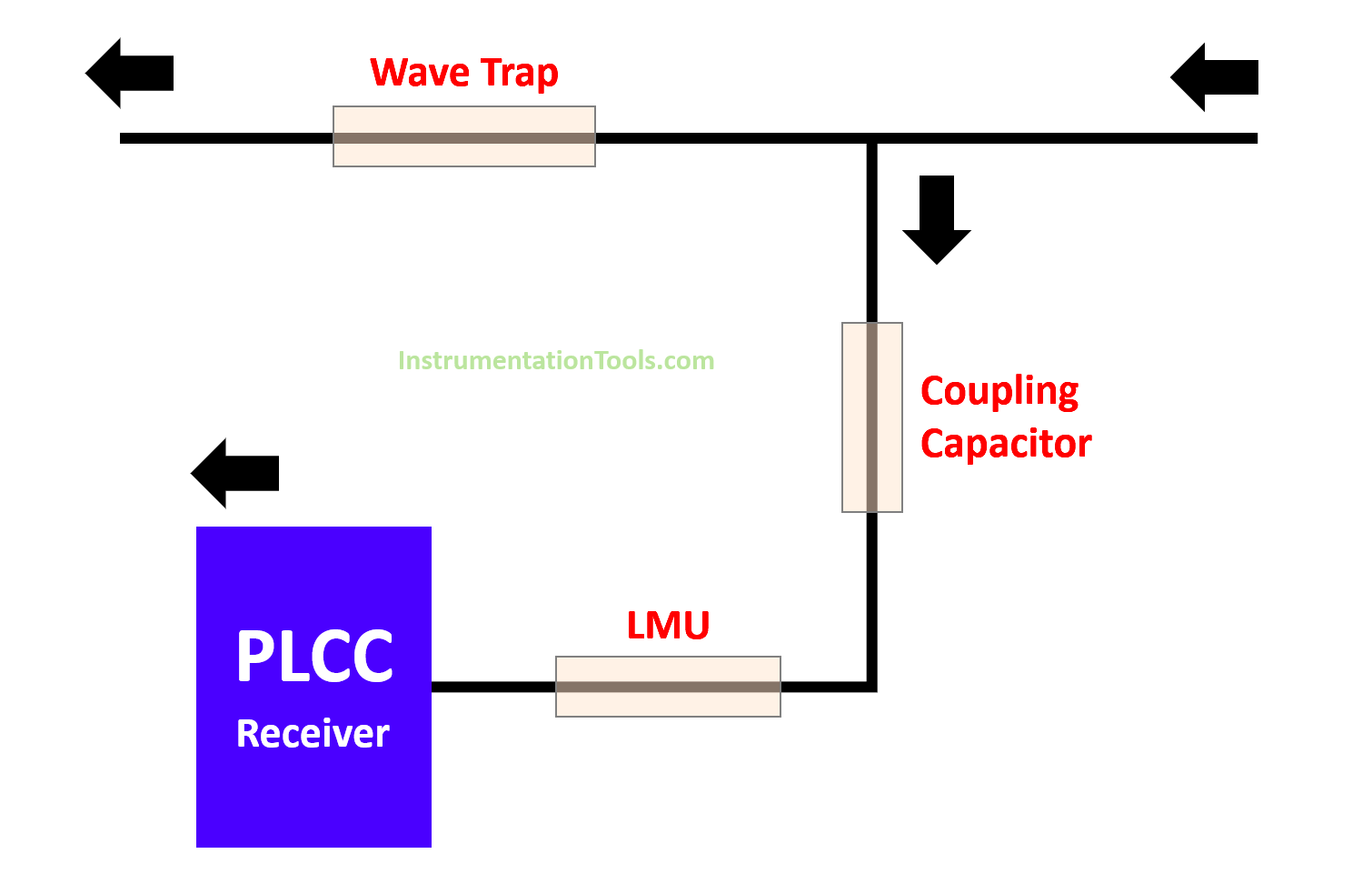
Next comes the coupling capacitor. It works in inverse proportion to the frequency. As the frequency increases, the reactance decreases and it allows them to pass. So, naturally, it will block the power signals from passing through it.

LMU is a line-matching unit. LMU is used as a coupling device and provides proper communication signals with optimum impedance matching, to the PLCC receiver.

Thus, due to this setup, we get low-frequency output at the wave trap and desired high-frequency data signal at the coupling capacitor.

In this way, we understand the concept of a line or wave trap.

If you liked this article, then please subscribe to our YouTube Channel for Electrical, Electronics, Instrumentation, PLC, and SCADA video tutorials.

You can also follow us on Facebook and Twitter to receive daily updates.

Read Next:

  • Electrical Drawings
  • Motor Cooling Methods
  • SCADA in Power System
  • What is a Buchholz Relay?
  • Motor Winding Sensors
Don't Miss Our Updates
Be the first to get exclusive content straight to your email.
We promise not to spam you. You can unsubscribe at any time.
Invalid email address
You've successfully subscribed !

Continue Reading

How does an Electric Motor Operate? – AC Motor Fundamentals
Motor Control Signal Interface
Various Control Methods in Servo Motor Drives
Why is the Humming Sound Produced in Transformer?
What is an ELV System? – Extra Low Voltage
What is a Bus Coupler in Electrical Panel?
Share This Article
Facebook Whatsapp Whatsapp LinkedIn Copy Link
Share
Leave a Comment

Leave a Reply Cancel reply

Your email address will not be published. Required fields are marked *

Stay Connected

128.3kFollowersLike
69.1kFollowersFollow
210kSubscribersSubscribe
38kFollowersFollow

Categories

Explore More

Difference Between MCB and RCBO
Effects of Long Distance Cables between VFD and Motor
What is a Submersible Pump? Principle Advantages Disadvantages
Electrical Cabinet Air Conditioner – Enclosure Cooling, Maintenance
Acceptable Earth Resistance Values
Motor Inrush Current Measurements
All About Electric Fence Gates
Dahlander Motors – Principle, Advantages, Disadvantages

Keep Learning

Benefits of SIMOCODE over Intelligent MCC

Benefits of SIMOCODE over Intelligent MCC

Electrical Power Grid Automation

Electrical Power Grid Automation

Difference between Servo Motor and DC Motor

Difference between Servo Motor and DC Motor

RDOL starter

What are DOL and RDOL starters? Advantages, Disadvantages

Emergency Stop Push button

Emergency Stop Switch Spurious Trip

running two single-phase induction motors sequentially

Control Two Motors in Sequence after Time Delay – Circuit, Operation

Most Asked Questions on Servo Motor

Most Asked Questions on Servo Motor (Answers)

Constant Torque Load of Electrical Motor

Types of Motor Loads – Constant & Variable Torque, Horsepower

Learn More

Target Meter Principle

Target Flow Meter – Working Principle, Advantages, Disadvantages

Garage Door Roller Shutter

Shutter Door Control using Motor and Limit Switches

P&ID Guidelines for Storage Tanks

P&ID Guidelines for Storage Tanks

PLC Programming Limit Switch

PLC Programming Example using Limit Switch

ControlLogix

Difference Between CompactLogix and ControlLogix

Voltage Polarities

Voltage Polarity and Current Direction

Hard-Wired Control Logic for the Pressure Alarm

Hard-Wired Control Logic for the Pressure Alarm

Material Certificate versus Positive Material Identification (PMI)

Material Certificate versus Positive Material Identification (PMI)

Menu

  • About
  • Privacy Policy
  • Copyright

Quick Links

  • Learn PLC
  • Helping Hand
  • Part Time Job

YouTube Subscribe

Follow US
All rights reserved. Reproduction in whole or in part without written permission is prohibited.
Welcome Back!

Sign in to your account

Username or Email Address
Password

Lost your password?