Inst ToolsInst ToolsInst Tools
  • Ask
  • Courses
  • Videos
  • Q & A
    • Interview
      • Instrumentation
      • Electronics
      • Electrical
      • Practical Questions
    • MCQ
      • Instrumentation MCQ
      • Electrical MCQ
      • Electronics MCQ
      • Control Systems MCQ
      • Analog Electronics MCQ
      • Digital Electronics MCQ
      • Power Electronics MCQ
      • Microprocessor MCQ
      • Multiple Choice Questions
  • EE
    • Electronics
      • Electronics Q & A
      • Electronic Basics
      • Electronic Devices & Circuits
      • Electronics Animation
      • Digital Electronics
    • Electrical
      • Electrical Basics
      • Electrical Q & A
      • Power Electronics
      • Electrical Machines
      • Electrical Animation
      • Power Systems
      • Switchgear & Protection
      • Transmission & Distribution
  • Measure
    • Control Valves
    • Calibration
    • Temperature
    • Pressure
    • Flow
    • Level
    • Analyzers
    • Switches
    • Vibration
    • Solenoid Valve
  • Control
    • PLC Tutorials
    • Control Systems
    • Safety Instrumented System (SIS)
    • Communication
    • Fire & Gas System
  • More
    • Design
    • Tools
    • Animation
    • Basics
    • Formulas
    • Standards
    • TextBooks
    • Common
    • Software
    • Excel Tools
    • Erection & Commissioning
    • Process Fundamentals
    • Videos
    • Books
Search
All rights reserved. Reproduction in whole or in part without written permission is prohibited.
Reading: Vibration Switch Working Principle
Share
Notification Show More
Font ResizerAa
Inst ToolsInst Tools
Font ResizerAa
  • Courses
  • PLC Tutorials
  • Control Systems
Search
  • Ask
  • Courses
  • Videos
  • Q & A
    • Interview
    • MCQ
  • EE
    • Electronics
    • Electrical
  • Measure
    • Control Valves
    • Calibration
    • Temperature
    • Pressure
    • Flow
    • Level
    • Analyzers
    • Switches
    • Vibration
    • Solenoid Valve
  • Control
    • PLC Tutorials
    • Control Systems
    • Safety Instrumented System (SIS)
    • Communication
    • Fire & Gas System
  • More
    • Design
    • Tools
    • Animation
    • Basics
    • Formulas
    • Standards
    • TextBooks
    • Common
    • Software
    • Excel Tools
    • Erection & Commissioning
    • Process Fundamentals
    • Videos
    • Books
Follow US
All rights reserved. Reproduction in whole or in part without written permission is prohibited.
Inst Tools > Blog > Switches > Vibration Switch Working Principle

Vibration Switch Working Principle

Last updated: April 18, 2019 3:18 pm
Editorial Staff
Switches Vibration Measurement
5 Comments
Share
2 Min Read
SHARE

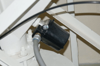
A vibration switch is a device that recognizes the amplitude of the vibration to which it is exposed and provides some sort of response when this amplitude exceeds a predetermined threshold value.

Contents
Vibration Switch Working PrincipleWhy use a vibration switch?

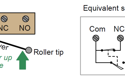
The switch response is typically an electrical contact closure or contact opening. The electrical contact may be either an electromechanical relay or solid-state device.

Vibration Switch Working Principle

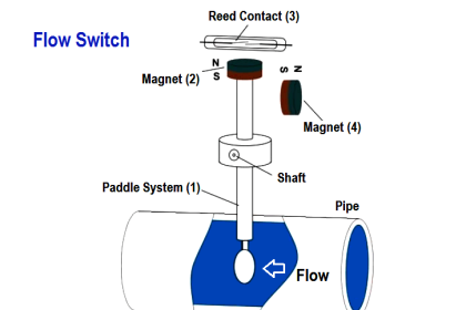
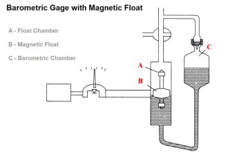
Vibration Switch is working according to the pendulum switching principle.

Mechanical Vibration Switch

A swinging permanent magnet holds a magnetic switch situated below in a particular position. Due to vibration, the magnetic field between Reed Switch and magnet changes.

Thus the switch is actuated resulting in the stoppage of the equipment. The responding sensitivity of the system can be changed by adjusting the gap between switch and magnet. Thus vibrations with amplitude below a set value can be suppressed.

Also Read : What is Keyphasor ?

The free pendulum length and the responding frequency of the switch with a frequency slider can be adjusted exactly to the natural frequency of the equipment to be protected.

Why use a vibration switch?

Vibration switches are primarily used for protecting critical machinery from costly destructive failure by initiating an alarm or shutdown when excessive vibration of the machinery is detected.

Conversely, a vibration switch can be utilized to warn when there is an absence of vibration, such as when a conveyor ceases to function due to a broken drive belt.

Applications include all types of rotating or reciprocating machinery such as cooling tower fans, pumps, compressors etc.

Don't Miss Our Updates
Be the first to get exclusive content straight to your email.
We promise not to spam you. You can unsubscribe at any time.
Invalid email address
You've successfully subscribed !
Switch Types and Common Terminology
Electromagnetic and Conductive limit switches Principle
Speed Probe Working Principle
Side Mounting Float Switch Working Principle
Working Principle of Flow Switch with Animation
Share This Article
Facebook Whatsapp Whatsapp LinkedIn Copy Link
Share
5 Comments
  • Lucimara Moreira sirilo says:
    October 14, 2016 at 9:37 am

    Adorei vcs estão e ajudando muito. Translated : Loved you guys are and helping much

    Reply
  • Maham Ali says:
    October 15, 2016 at 4:25 pm

    Very nice information and very helpful.

    Reply
  • George Ibraheem Yokhana says:
    April 26, 2018 at 5:27 pm

    Welcome Colleagues : As a matter of fact ,the above vibration switch was installed on our main pumps (Metric type ) for pumping white hydrocarbon products like Gasoline /Kerosene /Gas oil in Baiji pumping station -Iraq /the North Refinery and used to protect the main centrifugal pumps from Vibration which is one of the physical parameters we suppose to monitor and protect the equipment from up normal condition in case we have Vibration and Vibration created due to several reasons like misalignment between coupling (Pump and Motor driven unit ) / Air Bubbles inside the suction of the main pump / the base of the pump ..etc

    so we have two types of set point -one for Alarm and the second for Shut Down
    with units named or of abbreviation G so we have for example 3G or 4G ..so on also another mechanical vibration switch type we have and installed on the body of the main motor which protects 3.3 KV & 6.6 KV from vibration in case of any failure in the mechanical vibration installed on pump or other reasons for vibration to protect main motors

    Reply
  • Junaid says:
    August 14, 2018 at 12:26 pm

    Sir please provide more information

    Reply
  • n ramanaiah says:
    March 19, 2023 at 11:37 pm

    explain the vibration sensor working principle with animation.

    Reply

Leave a Reply Cancel reply

Your email address will not be published. Required fields are marked *

Stay Connected

128.3kFollowersLike
69.1kFollowersFollow
208kSubscribersSubscribe
38kFollowersFollow

Categories

Recent Comments

  • Guifty Shimica on Top Non-PLC Certification Courses for Automation Professionals
  • Guifty Shimica on Top Non-PLC Certification Courses for Automation Professionals
  • MIHARITSOA Aina Sitraka on Top Non-PLC Certification Courses for Automation Professionals
  • Vaishnavi on Free Instrumentation Course for Trainee Engineers

Related Articles

Proximity Switch Working Animation

Proximity Switch Working Animation

Types of Limit Switches

Types of Limit Switches – Principle, Advantages, Disadvantages

Switch NO or NC Contact

Normally-open and Normally-closed Switch Contacts

Boiler Level Switch

Float level switch Principle

AND Logic in Bently Nevada Vibration System

AND Logic in Bently Nevada Vibration System

Limit Switch Installation

What is a Limit Switch ?

Process Switches Normal Status

Define Normal Status for each of the Process Switch

Magnetic Float Level Switch Working Animation

More Articles

Sensors and Transducers Test

Sensors and Transducers Test

Power Electronics Objective Questions

Current Source Inverters Objective Questions

Paddlewheel flowmeter principle

What is a Paddle Wheel Flow Meter?

Simulator in S7-1200 and S7-1500 PLC

How to Work With Simulator in S7-1200 and S7-1500 PLC?

What is a Condensate Pot? How to Install it?

Difference Between CNC Machine and VMC Machine

Difference Between CNC Machine and VMC Machine

PLC Load Memory

What is Resources Tab in the Siemens PLC?

DP transmitter with Manifold

Pressure Transmitter Manifolds

Follow US
All rights reserved. Reproduction in whole or in part without written permission is prohibited.
Welcome Back!

Sign in to your account

Username or Email Address
Password

Lost your password?