Inst ToolsInst ToolsInst Tools
  • Courses
  • Automation
    • PLC
    • Control System
    • Safety System
    • Communication
    • Fire & Gas System
  • Instrumentation
    • Design
    • Pressure
    • Temperature
    • Flow
    • Level
    • Vibration
    • Analyzer
    • Control Valve
    • Switch
    • Calibration
    • Erection & Commissioning
  • Interview
    • Instrumentation
    • Electrical
    • Electronics
    • Practical
  • Q&A
    • Instrumentation
    • Control System
    • Electrical
    • Electronics
    • Analog Electronics
    • Digital Electronics
    • Power Electronics
    • Microprocessor
  • Request
Search
  • Books
  • Software
  • Projects
  • Process
  • Tools
  • Basics
  • Formula
  • Power Plant
  • Root Cause Analysis
  • Electrical Basics
  • Animation
  • Standards
  • 4-20 mA Course
  • Siemens PLC Course
Reading: Why V/f Ratio is kept Constant in VFD?
Share
Font ResizerAa
Inst ToolsInst Tools
Font ResizerAa
  • Courses
  • Design
  • PLC
  • Interview
  • Control System
Search
  • Courses
  • Automation
    • PLC
    • Control System
    • Safety System
    • Communication
    • Fire & Gas System
  • Instrumentation
    • Design
    • Pressure
    • Temperature
    • Flow
    • Level
    • Vibration
    • Analyzer
    • Control Valve
    • Switch
    • Calibration
    • Erection & Commissioning
  • Interview
    • Instrumentation
    • Electrical
    • Electronics
    • Practical
  • Q&A
    • Instrumentation
    • Control System
    • Electrical
    • Electronics
    • Analog Electronics
    • Digital Electronics
    • Power Electronics
    • Microprocessor
  • Request
Follow US
All rights reserved. Reproduction in whole or in part without written permission is prohibited.
Inst Tools > Blog > Electrical Basics > Why V/f Ratio is kept Constant in VFD?

Why V/f Ratio is kept Constant in VFD?

When motor running through VFD the V/f ratio is kept constant in order to minimize the eddy current and hysteresis losses.

Last updated: March 23, 2021 3:07 pm
Editorial Staff
Electrical Basics
No Comments
Share
4 Min Read
SHARE

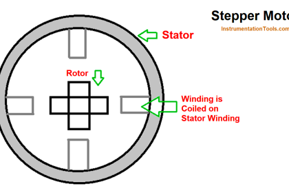
VFD is used for speed control of induction motor to save energy and for better process control. Let us first understand the working of induction motor. The motor converts electrical energy into mechanical energy.

Contents
V/f Ratio Constant in VFDWhat happens if flux is increased above the rated capacity?

However, one more intermediate stage of conversion before converting the electrical energy into mechanical energy is the magnetic energy. Thus, the motor converts the electrical energy into magnetic energy and then the magnetic energy is again converted into electrical energy and finally to mechanical energy.

The motor has its rated magnetic energy handling capacity. The magnetic energy or air gap power depends on the flux. The core of the motor is designed to carry the rated flux. More than the rated flux should never be allowed to pass through the core.

V/f Ratio Constant in VFD

Let us see on what factors the magnetic flux of the motor depends.

If AC voltage is applied to stator of the induction motor, the flux is generated. The flux generated is in phase with the applied voltage.

Φ = Φm Sinωt

According to the Faraday’s law of electromagnetic induction, the self EMF induced generated in the stator is expressed as;

e = – N (dΦ/dt)

e = – N [(dΦm Sinωt/dt)]

e = – NwΦm Cosωt

e = 2πfN Φm Cosωt

e = Em Cosωt

Here Em = 2πfN Φm

RMS value of voltage induced;

erms = Em/√2

erms = (2πfN Φm) /√2

erms = 4.44 Φm f N

Φ = erms / 4.44 f N

Φ =e/f = v/f

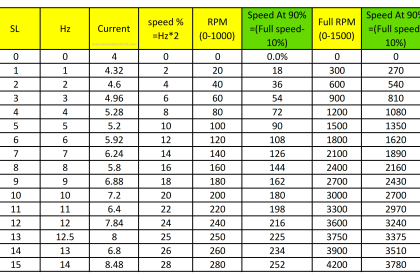
Thus the flux generated in the stator depends on the ratio of the volt/Hz.

In VFD motor, speed is controlled by changing the frequency, as the speed of the motor is proportional to the frequency.

N = 120f/p

The speed of the motor can be changed by varying the frequency, however the voltage needs to be increased or decreased in the same proportion of the frequency to maintain the constant flux in the motor.

The PWM inverter of the VFD maintain the constant V/f ratio in order to maintain the constant flux in the motor. Suppose an induction motor of rating 440 volts,50 Hz is to be operated through VFD and if the speed is half of its rated speed, then PWM inverter output 25 Hz AC.

If voltage remains 400 volts then the ratio of v/f = 400/25 =16. The motor will experience double flux of its rated flux capacity in this case. Therefore when frequency is 25 Hz, the voltage will be 200 volts and v/f ratio is equal to 8.

What happens if flux is increased above the rated capacity?

Higher flux than its rated capacity leads to increased eddy current and hysteresis losses. The increased losses cause the heating of the core and as a result of this the insulation of core will get damaged.

Therefore, when motor running through VFD the V/f ratio is kept constant.

Author: Satyadeo Vyas

If you liked this article, then please subscribe to our YouTube Channel for Instrumentation, Electrical, PLC, and SCADA video tutorials.

You can also follow us on Facebook and Twitter to receive daily updates.

Read Next:

  • Torque Boosting in Variable Frequency Drive
  • Variable Frequency Drive Working Principle
  • Motor Speed Control using VFD and PLC
  • AC Motor Speed Control
  • Magnetism
Don't Miss Our Updates
Be the first to get exclusive content straight to your email.
We promise not to spam you. You can unsubscribe at any time.
Invalid email address
You've successfully subscribed !

Continue Reading

Differences between Watts and Volt Amps
What is a Damper? Types of Dampers in HVAC
Proper Sizing of Conductors
What is a Link Box?
What are Inverse Time and Instantaneous Trip Circuit Breakers?
Motor Control Signal Interface
Share This Article
Facebook Whatsapp Whatsapp LinkedIn Copy Link
Share
Leave a Comment

Leave a Reply Cancel reply

Your email address will not be published. Required fields are marked *

Stay Connected

128.3kFollowersLike
69.1kFollowersFollow
210kSubscribersSubscribe
38kFollowersFollow

Categories

Explore More

Electrical Contactor Interlocking Circuit Explained
Difference Between HV and LV Cables
What is an Instrument Transformer? – Types, Principle, Advantages
What is a VFD? – Theory, Advantages, Disadvantages
Motor Classic Control Circuits using Single Push button
Basics of Electrical Transformer
Cathodic Protection – Sacrificial Anodic and Impressed Current
Electrical Feeder Automation in Smart Grid

Keep Learning

Intelligent Motor Control Center

What is an Intelligent Motor Control Center? – IMCC

What is a Magnetic Field

Difference Between Electric Field and Magnetic Field

Arc Protective Clothing

What is Arc Protective Clothing? – Importance, Features, Materials

Motor Slip Calculation

Electrical Motor Terms and Concepts

What is a Lightning Arrester? How does it work?

How to Locate Faults in Cables? - Fault Analysis and Location

How to Locate Faults in Cables? – Fault Analysis & Location

Motor Control On-Delay Timers Circuit

Motor Control Timer Circuit – Automatic Motor START and STOP

Understanding Protection Relays

Understanding Protection Relays – 50, 50N, 51, 51N

Learn More

4-20mA Current Loop

Basics of 4-20mA Current Loop

What is Barring Gear Logic? Why is it Required in the Steam Turbine?

Differential Pressure Sensor with pair of Strain Gauges

Differential Pressure Sensor with Pair of Strain Gauges

water treatment station

What is a Vent Filter? – Water Treatment Plant

Temperature Transmitter with Thermocouple

Thermocouple Extension and Compensating Cables

Single Phase Preventer Relay

Working Principle of Single Phase Preventer Relay

Manchester encoding

Foundation Fieldbus Electrical Parameters

Humidity sensor Working Principle

Humidity Sensor Working Principle

Menu

  • About
  • Privacy Policy
  • Copyright

Quick Links

  • Learn PLC
  • Helping Hand
  • Part Time Job

YouTube Subscribe

Follow US
All rights reserved. Reproduction in whole or in part without written permission is prohibited.
Welcome Back!

Sign in to your account

Username or Email Address
Password

Lost your password?