In this post, we will see the use of isolators and barriers in an electrical panel.
Isolators
The two most used types of analog signals in instrumentation are 0-10 V and 4-20 mA. Of these, the widely popular one that is used is the 4-20 mA type one.
The most important advantage of the current signal over voltage signal is wiring. A voltage transmitter will mostly require a 4-wire connection.
But, a current transmitter can be configured with only 2 wires in connection. Current transmitters are less prone to electromagnetic interference.
Also, if the distances are long for connection, resistances increase with distance which causes a larger voltage drop. This problem does not occur in current transmitters.
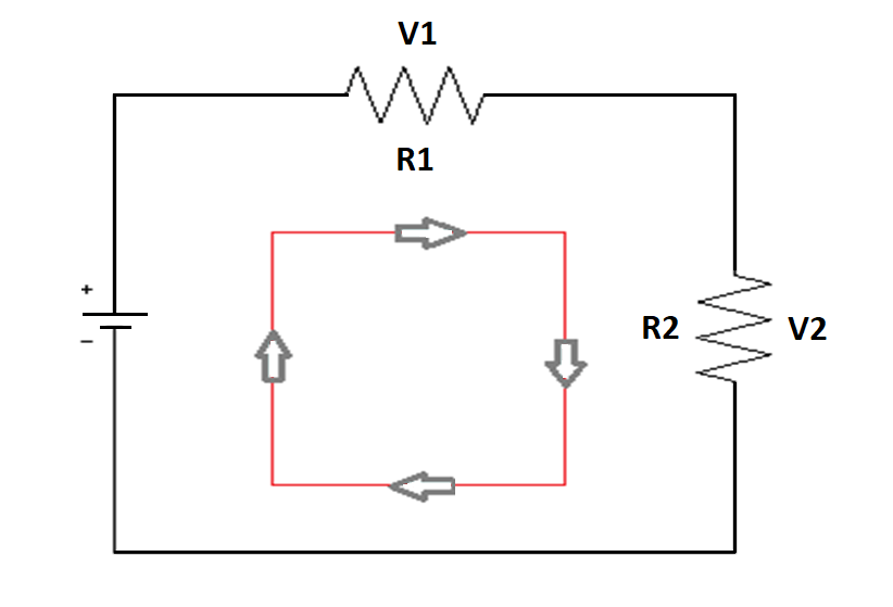
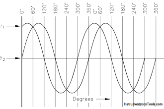
Now, let us understand first how a current loop flows in an analog circuit by simple Ohm’s law. Refer the first image.
The circuit consists of a power supply and two loads. The power supply will give the voltage required to drive the current loop.
Through current passing across each load, voltage drop occurs each of them and will vary according to the resistance available.
However, current remains the same in the whole circuit. If you remember, according to Ohm’s law, V=I*R.
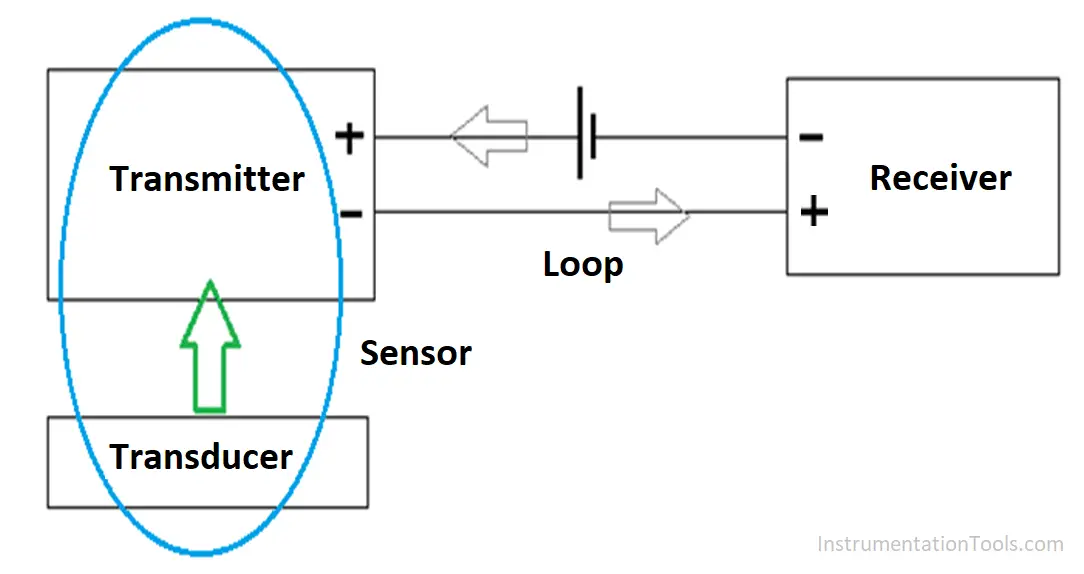
Now, let us consider the second image below. The sensor consists of a transducer and transmitter.
The transducer provides the physical signal and the transmitter converts this into an electrical signal.
A power source is used to produce the required electrical signal and drive the current in the circuit.
The loop is nothing but the wiring which carries the signal from transmitter to receiver and then back to it.
But, even 4-20 mA has some demerits. One of the main problems faced is non-isolation.
As the word denotes, isolation is a method of isolating the ground loop leakages, common-mode voltage issues, and electrical noise from the main analog signal.
These problems are commonly faced in a 4-20 mA loop and if there is no proper isolation between the transmitter and receiver, fluctuations can occur at the receiver side and this can hamper the overall performance of the system.
Isolation will filter only the analog signal to the receiver and will eliminate noise and fluctuations in its input side only.
Isolation in a PLC control panel can be done by two methods – by connecting an isolator between the sensor or any field device and PLC; or by using an isolated PLC channel. We will look the use of an isolator in the electrical panel.
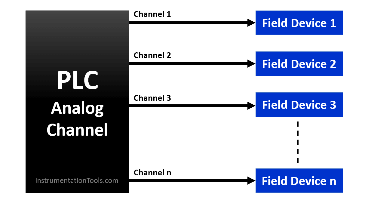
Refer to the below image. It is a simple connection where the first part shows the wiring without an isolator in between the PLC analog card and field devices.
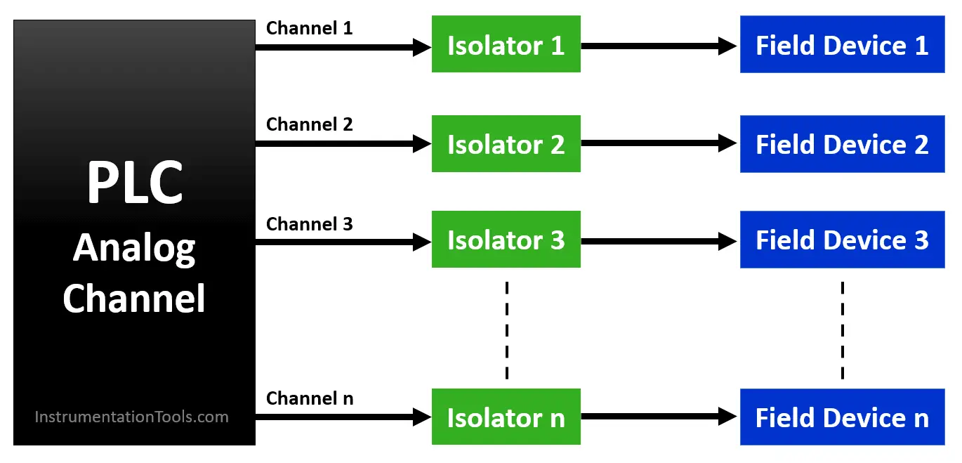
The below image shows the PLC analog channel with isolators. Each channel or field device requires one isolator between them.
Applications of Isolators
The isolator has the following applications:
It can remove ground loop formation in an analog circuit. A ground loop occurs when there is more than one ground connection path between two devices.
Due to different earth potentials sometimes, an antenna-type loop current will form which will flow from ground to ground and will interfere with the main signal-carrying current and disrupt its performance.
The isolator will basically pass or filter only the main signal-carrying current and will nullify the leakage current.
Isolators can be used for loads with high impedance and connected at a large distance from the receiver or controller
Isolators eliminates common-mode signals. This ensures you can connect signals of different common-mode voltages.
For example, a transmitter may be referenced to +24V whereas the PLC may be referenced to ground.
Due to common-mode voltage differences arising, it can disrupt signal performance. The isolator will eliminate this and will provide a pure analog signal between the lines.
Barriers
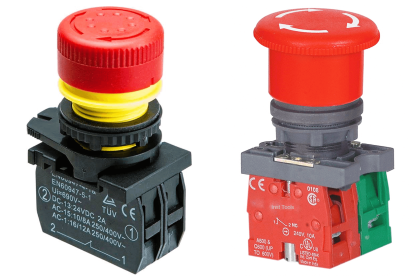
Intrinsic devices use a limited amount of thermal and electrical energy which cannot cause fire or explosion in hazardous areas.
Some methods must be used in an electrical panel to protect both the field environment and the instrument/panel environment.
Mostly, in hazardous areas where there are high chances of ignition or other forms of damage, you have to take special care to protect the field instruments from damaging themselves or the instrumentation devices inside the panel.
This task can be achieved by the use of barriers. A barrier is a device which keeps the available electrical energy low enough so that the ignition cannot occur.
Similar to an isolator, it is also connected between the field equipment and the controller.
It generally consists of three main components – fuse, zener diode and a current limiting resistor. The fuse restricts the fault power, the zener diode restricts the fault voltage and the current limiting resistor limits the fault current.
Now, in more advanced times, there are more flexible types of barriers and isolators available. Some give dual output from a single input, some convert 0-10 V signal into 4-20 mA signal and many others.
The role of both the isolators and barriers are more or less similar. They usually protect the environment from any damage.
By forming itself as a wall between hazardous areas and non-hazardous areas, it basically restricts the transfer of fault energy between both of them.
Author: Viral Nagda
If you liked this article, then please subscribe to our YouTube Channel for Instrumentation, Electrical, PLC and SCADA video tutorials.
You can also follow us on Facebook and Twitter to receive daily updates.
Read Next:


Sir, please change the first pharagraph of barrier as it is written incorrect.
Corrected pharagraph: “Intrinsic devices are that which generate a certain amount of thermal and electrical energy which cannot cause fire or explosion in hazardous area.”