ULTRASONIC TECHNOLOGY
Ultrasonic is a non-contact level measurement method that uses sound waves to determine the process material being measured.
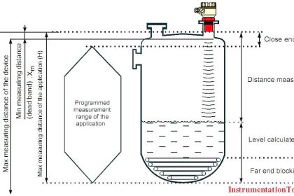
Ultrasonic transmitters operate by sending a sound wave, generated from a piezo electric transducer, to the media being measured. The device measures the length of time it takes for the reflected sound wave to return to the transducer.
A successful measurement depends on reflection from the process material in a straight line back to the transducer.
However, there are various influences that affect the return signal. Factors such as dust, heavy vapors, tank obstructions, surface turbulence, foam and even surface angles can affect the returning signal.
That is why the conditions that determine the characteristics of sound must be considered when using Ultrasonic measurement.
Other problematic aspects of Ultrasonic transmitters to consider include:
Vacuum Applications
- Sound must travel through a medium (usually air)
- The absence of air molecules prevents the propagation of sound waves
Surface Condition
Angles
- Sound waves must be sent and received in a straight line
- Reflective surfaces must be flat (i.e. Non-agitated/Non-turbulent condition)
Irregularities
- Foam and other debris collected on the surface of the liquid which absorbs the sound waves and impedes their return sound travel to the sensor
Temperature Limits
- Ultrasonic units are typically plastic with a maximum temperature of 140˚F (60˚C)
- Varying process temperatures may generate inaccurate readings
Pressure Limits
- Ultrasonic devices are not intended for extreme pressure limits
- Maximum working pressures should not exceed of 30 PSIG (2 Bar)
Environmental Conditions
- Ultrasonic devices should be mounted in a predictable environment
- Vapor, condensing humidity, and other contaminates that change the speed of sound through air greatly effect the accuracy of the return signal
Also Read: Ultrasonic Level Transmitter Working Animation
The most popular benefit of through-air measurement principles like Ultrasonic, Radar, or Laser measurement is the fact that the measuring signal never comes in contact with the product being measured. But if you think about it, this ‘fact’ is not entirely accurate. Take Ultrasonics for example: When sound energy leaves the transducer, it travels through air at 1,125 feet per second until it reaches its target (i.e. liquid surface).
Similar to all other “non-contacting” type of level measurement, at some point the measuring signal must come in contact with the liquid surface before it begins its return trip back to the sensor. This not only explains why the air quality between the sensor and liquid surface can be problematic, but also why the quality of the liquid surface needs to be accounted for. Every disturbance it picks up on its way down and back will disturb the actual level measurement information in the signal
It is important to understand that Ultrasonic transmitters will provide a sensible solution, when properly applied. Remember, the Ultrasonic transmitter is just as good as the echo it receives.
GUIDED WAVE RADAR (GWR) TECHNOLOGY
Guided Wave Radar (GWR) is a contacting level measurement method that uses a probe to guide high frequency, electromagnetic waves as they travel down from a transmitter to the media being measured.
GWR is based upon the principle of Time Domain Reflectometry (TDR), which is an electrical measurement technique that has been used for several decades in various industrial measurement applications; among its first fields of application was the location of cable damage. In level measurement, however, TDR has only been used for a little over a decade.
With TDR, a low-energy electromagnetic pulse is guided along a probe. When the pulse reaches the surface of the medium being measured, the pulse energy is reflected up the probe to the circuitry which then calculates the fluid level from the time difference between the pulse sent and the pulse reflected. The sensor can output the analyzed level as a continuous measurement reading through its analog output, or it can convert the values into freely positionable switching output signals.
GWR is suitable for a variety of level measurement applications including:
Unstable Process Conditions
- Changes in viscosity, density, or acidity do not effect accuracy
Agitated Surfaces
- Boiling surfaces, dust, foam, vapor do not effect device performance
- Recirculating fluids, propeller mixers, aeration tanks
Extreme Operating limits
- GWR performs well under extreme temperatures up to 600ºF (315ºC)
- Capable of withstanding pressures up to 580 PSIG (40 Bar)
Fine Powders & Sticky Fluids
- Vacuum tanks with used cooking oil
- Paint, latex, animal fat and soy bean oil
- Saw dust, carbon black, titanium tetrachloride, salt, grain
Also Read: Guided Wave Radar Level Transmitter Working Animation
One of the most common misconceptions of GWR is the effects of product build-up on the probe. One would think that if you have a mass of product stuck to the probe, or a coating of product throughout the entire probe length, that the signal would misidentify the true liquid surface.
This in fact is not the case with advanced GWR technology. The radar signal of GWR has a very large detection area around the probe covering 360˚ of area over several feet of coverage. When this pulse energy comes in contact with a mass of product on the probe, the signal is returned and analyzed to see if it is the true liquid level.
Since the liquid level always has a larger signal return than the smaller mass that is sticking on the probe, the liquid surface is easily identifiable. The advanced algorithms developed over the last decade have made this contacting form of level measurement the ideal solution for even the stickiest of fluid applications.
Advantages of GWR in the level industry are endless. Unlike older technologies, GWR offers measurement readings that are independent of chemical or physical properties found in the contact media. Additionally, GWR performs equally well in liquids and solids.
The chart below compares some important features between Ultrasonic and Guided Wave Radar

Also Read: Zero Suppression & Zero Elevation in Level Measurement