Inst ToolsInst ToolsInst Tools
  • Courses
  • Automation
    • PLC
    • Control System
    • Safety System
    • Communication
    • Fire & Gas System
  • Instrumentation
    • Design
    • Pressure
    • Temperature
    • Flow
    • Level
    • Vibration
    • Analyzer
    • Control Valve
    • Switch
    • Calibration
    • Erection & Commissioning
  • Interview
    • Instrumentation
    • Electrical
    • Electronics
    • Practical
  • Q&A
    • Instrumentation
    • Control System
    • Electrical
    • Electronics
    • Analog Electronics
    • Digital Electronics
    • Power Electronics
    • Microprocessor
  • Request
Search
  • Books
  • Software
  • Projects
  • Process
  • Tools
  • Basics
  • Formula
  • Power Plant
  • Root Cause Analysis
  • Electrical Basics
  • Animation
  • Standards
  • 4-20 mA Course
  • Siemens PLC Course
Reading: Ultrasonic Flow Meters Working Principle
Share
Font ResizerAa
Inst ToolsInst Tools
Font ResizerAa
  • Courses
  • Design
  • PLC
  • Interview
  • Control System
Search
  • Courses
  • Automation
    • PLC
    • Control System
    • Safety System
    • Communication
    • Fire & Gas System
  • Instrumentation
    • Design
    • Pressure
    • Temperature
    • Flow
    • Level
    • Vibration
    • Analyzer
    • Control Valve
    • Switch
    • Calibration
    • Erection & Commissioning
  • Interview
    • Instrumentation
    • Electrical
    • Electronics
    • Practical
  • Q&A
    • Instrumentation
    • Control System
    • Electrical
    • Electronics
    • Analog Electronics
    • Digital Electronics
    • Power Electronics
    • Microprocessor
  • Request
Follow US
All rights reserved. Reproduction in whole or in part without written permission is prohibited.
Inst Tools > Blog > Animation > Ultrasonic Flow Meters Working Principle

Ultrasonic Flow Meters Working Principle

Ultrasonic flow meters operate using difference in time travelled by the two ultrasonic waves is directly proportional to the flow velocity.

Last updated: November 1, 2023 5:48 am
Editorial Staff
Animation Flow Measurement
2 Comments
Share
2 Min Read
SHARE

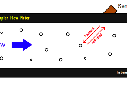
Ultrasonic flow meters operate using the transit-time differential method. The Transit-time differential measurement is based on a simple physical fact.

Contents
Ultrasonic Flow MetersPros and Cons of Ultrasonic Flow Meters

Imagine two canoes crossing a river on the same diagonal line, one with the flow and the other against the flow. The canoe moving with the flow needs much less time to reach the opposite bank.

Ultrasonic Flow Meters

Ultrasonic Flow Meters Working Principle

Ultrasonic waves behave exactly the same way. A sound wave traveling in the direction of the flow of the product is propagated at a faster rate than one traveling against the flow (vAB > vBA).

Transit times tAB and tBA are measured continuously. The difference (tBA – tAB) in time traveled by the two ultrasonic waves is directly proportional to the mean flow velocity (vm).

Where,

  • tAB is the Time required for an ultrasonic wave to travel from Sensor A to B sensor
  • tBA is the Time required for an ultrasonic wave to travel from Sensor B to A sensor

Pros and Cons of Ultrasonic Flow Meters

Ultrasonic Flow Meters Advantages & Disadvantages

If you liked this article, then please subscribe to our YouTube Channel for Instrumentation, Electrical, PLC, and SCADA video tutorials.

You can also follow us on Facebook and Twitter to receive daily updates.

Read Next:

  • Wedge Flow Meter Principle
  • Variable Area Flow Meters
  • Ultrasonic Level Sensor Principle
  • Calibrate Different Flow Meter
  • What is a Vortex Flow Meter?
Don't Miss Our Updates
Be the first to get exclusive content straight to your email.
We promise not to spam you. You can unsubscribe at any time.
Invalid email address
You've successfully subscribed !

Continue Reading

4-20mA Junction Box versus Fieldbus (FF) Junction Box
Ultrasonic Level Transmitter Animation
Argonite/CO2 Flooding System Master & Slave Cylinder Operation
In-Line Flow Switch Working Principle and Animation
Why Viscosity is Not Included in the Orifice Equation?
Deluge System for Transformer Protection Animation
Share This Article
Facebook Whatsapp Whatsapp LinkedIn Copy Link
Share
2 Comments
  • Amar says:
    June 2, 2017 at 9:55 am

    Pls, hindi version available ?

    Reply
    • S Bharadwaj Reddy says:
      June 2, 2017 at 2:01 pm

      Hi, Open Any Article > In Right Side bottom, you can find language translate option, select your required language.

      Reply

Leave a Reply Cancel reply

Your email address will not be published. Required fields are marked *

Stay Connected

128.3kFollowersLike
69.1kFollowersFollow
210kSubscribersSubscribe
38kFollowersFollow

Categories

Explore More

What is a Turbine Flow Meter?
Gas chromatograph Working Animation
Basics of Differential Pressure Level Transmitters
Spring and Diaphragm Pneumatic Actuators
Different Flow Measurement Technologies
Network Switch Port Allocation Details
Principle of Flow Switch
Bubbler Level Measurement Animation

Keep Learning

Paddlewheel flowmeter principle

What is a Paddle Wheel Flow Meter?

Pressure and Temperature Compensation for Flow Transmitter

Why Pressure & Temperature Compensation required for Orifice Flow Meters ?

Float level gauge Principle

Float Type Level Indicator Principle

Encoder Principle

Encoder Working Principle

AND Gate Logic Animation

Digital Building Blocks – GATES

Radar Level Transmitter in Briddle level Measurement

Radar Level Transmitter in Briddle level Measurement

Orifice Plate Flow Requirements

What are the Orifice Plate Flow Requirements?

Vortex flow meter Bluff Body

Types of Vortex Flow Meter Sensors

Learn More

Temperature Transmitter Foundation Fieldbus Configuration

Foundation Fieldbus Temperature Transmitter Configuration

Feedback Pneumatic Load cell Objective Questions

Feedback Pneumatic Load cell Objective Questions

Single-Acting Air Compressor Cylinder

Reciprocating Compressors

Modbus Code

Modbus Relative Addressing

Microprocessors Objective Questions

Microprocessors Objective Questions – Set 7

Current-to-Percentage-Conversion

Formula for Current 4-20ma to Percentage Conversion

Ohms Law Objective Questions and Answers

Ohms Law Objective Questions and Answers

Basics of Valves Interview Questions & Answers

Basics of Valves Interview Questions & Answers

Menu

  • About
  • Privacy Policy
  • Copyright

Quick Links

  • Learn PLC
  • Helping Hand
  • Part Time Job

YouTube Subscribe

Follow US
All rights reserved. Reproduction in whole or in part without written permission is prohibited.
Welcome Back!

Sign in to your account

Username or Email Address
Password

Lost your password?