Inst ToolsInst ToolsInst Tools
  • Courses
  • Automation
    • PLC
    • Control System
    • Safety System
    • Communication
    • Fire & Gas System
  • Instrumentation
    • Design
    • Pressure
    • Temperature
    • Flow
    • Level
    • Vibration
    • Analyzer
    • Control Valve
    • Switch
    • Calibration
    • Erection & Commissioning
  • Interview
    • Instrumentation
    • Electrical
    • Electronics
    • Practical
  • Q&A
    • Instrumentation
    • Control System
    • Electrical
    • Electronics
    • Analog Electronics
    • Digital Electronics
    • Power Electronics
    • Microprocessor
  • Request
Search
  • Books
  • Software
  • Projects
  • Process
  • Tools
  • Basics
  • Formula
  • Power Plant
  • Root Cause Analysis
  • Electrical Basics
  • Animation
  • Standards
  • 4-20 mA Course
  • Siemens PLC Course
Reading: Types of Signals Based on Electromagnetic Compatibility (EMC Performance)
Share
Font ResizerAa
Inst ToolsInst Tools
Font ResizerAa
  • Courses
  • Design
  • PLC
  • Interview
  • Control System
Search
  • Courses
  • Automation
    • PLC
    • Control System
    • Safety System
    • Communication
    • Fire & Gas System
  • Instrumentation
    • Design
    • Pressure
    • Temperature
    • Flow
    • Level
    • Vibration
    • Analyzer
    • Control Valve
    • Switch
    • Calibration
    • Erection & Commissioning
  • Interview
    • Instrumentation
    • Electrical
    • Electronics
    • Practical
  • Q&A
    • Instrumentation
    • Control System
    • Electrical
    • Electronics
    • Analog Electronics
    • Digital Electronics
    • Power Electronics
    • Microprocessor
  • Request
Follow US
All rights reserved. Reproduction in whole or in part without written permission is prohibited.
Inst Tools > Blog > Common > Types of Signals Based on Electromagnetic Compatibility (EMC Performance)

Types of Signals Based on Electromagnetic Compatibility (EMC Performance)

Learn the types of signals based on electromagnetic compatibility (EMC Performance) in electrical and electronic circuits.

Last updated: August 28, 2023 3:38 pm
Viral Nagda
Common
No Comments
Share
5 Min Read
SHARE

A very common issue occurring in electrical and electronic circuits is electromagnetic interference. It is also called EMI in electrical terms. This problem hampers the performance of a circuit in a very big way, if not restricted in time. To tackle them, another term related to electrical circuits is EMC.

Contents
What Causes Electromagnetic Interference?EMC PerformanceClass-1 (Sensitive)Class-2 (Slightly sensitive)Class-3 (Slightly interfering)Class-4 (Interfering)

EMC stands for electromagnetic compatibility. It is the ability of electrical equipment and devices to restrict the EMI in their systems. Based on EMC, various types of signals are classified according to their performance. In this post, we will learn the types of signals based on EMC performance.

What Causes Electromagnetic Interference?

Everyone knows that the electrical field and magnetic field are related to each other. When electricity flows through a circuit, it produces a magnetic field around it. This theory is the base of electricity. Inversely, a moving magnetic field also produces an electric current. Electricity is nothing but the flow of electrons and atoms in it.

Atoms can be positively or negatively charged. Opposite poles attract each other and the same poles repel each other. This rapid movement of electrons produces a magnet like operation every time, thus generating a magnetic field.

Now, inversing the theory as discussed, a moving magnetic field indirectly pushes or pulls electrons in it. This flow of electrons generates an electric field near it. So, this base of electricity is the foundation of other theories.

Now, coming back to our concept, let us first understand how EMI is generated. Basically, electromagnetic interference can be man-made or natural. In natural causes, sources like lightning, solar storms, and solar flares produce high electrostatic discharges. When this discharge interacts with the electromagnetic field, it produces spikes and surges in such a way that signal distortion occurs.

This means, a normal electromagnetic field has some standard electrical and magnetic field calculations, which is suddenly disturbed by these interferences. It produces very high rates of changes in signals, thus distorting it.

Similarly, man-made interferences can be caused by high radio frequencies, improperly designed devices, high-power motors, transformers, or other types of conductors. The signals of high frequency are always emitted from them, which interferes with other electromagnetic fields, causing EMI.

EMC Performance
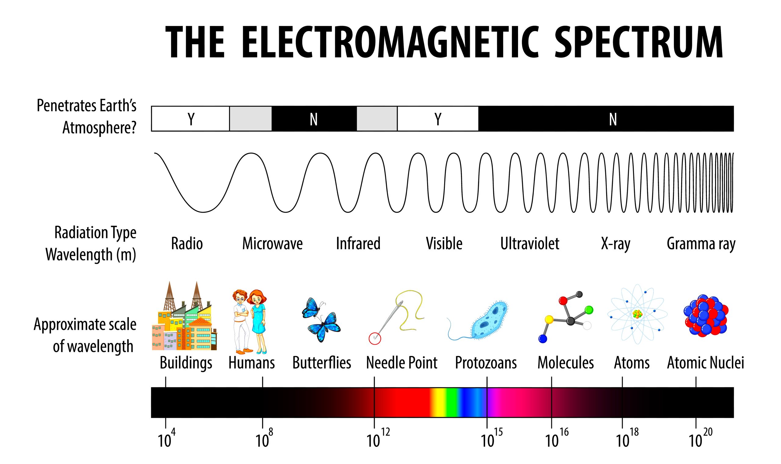
Electromagnetic

To reduce electromagnetic interference, the EMC term comes into the picture. As discussed earlier, EMC is the ability of devices to tackle electromagnetic interference and reduce its effect. This compatibility is the main factor for reducing interference.

So, the electrical circuits designed for EMC are classified in various categories. These circuits handle the electromagnetic noise according to their EMC factors. Based on this EMC performance, the signals are classified into four types:

Class-1 (Sensitive)

This is the lowest category of circuits, which has the highest effect of electromagnetic interference in it. They carry low-level signals like analog output, instrument transformers, measuring circuits, probes, and radio receivers. These signals are immediately affected by EMI and have very less EMC factors.

Class-2 (Slightly sensitive)

These cables are slightly sensitive to electromagnetic interference. They are low-level digital circuits, instrument transformers with digital outputs, control circuits for resistive load, and low-level DC power supplies. These signals can disturb class-1 signals too.

Class-3 (Slightly interfering)

These cables have fewer effects on EMI on them, but a negative point is that they start to disturb other lower-class signals. So, instead of being sensitive, they slowly categorize themselves into slightly interfering. They disturb class 1 and 2 signals.

They are control circuits for inductive loads (relay, contactor, coil), AC power supplies, and main power supplies for high-power devices. It is from these types of signals that they start to carry noise, though they themselves are less susceptible to EMI.

Class-4 (Interfering)

These cables are the least affected by EMI (highest levels of EMC), but the highest source of EMI disturbance for other cables. They disturb the other three classes’ cables. The types are welding machines, high-power circuits, electronic speed controllers, and SMPS. They are thus, also named as interfering signals.

In this way, we saw the various types of signals based on EMC performance.
Don't Miss Our Updates
Be the first to get exclusive content straight to your email.
We promise not to spam you. You can unsubscribe at any time.
Invalid email address
You've successfully subscribed !

Continue Reading

Measurement Unit Conversions
How Does Starlink Work?
Understanding RS-485 Communication
Introduction to MEMS (Microelectromechanical Systems)
What is an Instrument Skid? – Example of Metering Skid
Know the Best Path to Achieve SOA-C02 Exam Certification
Share This Article
Facebook Whatsapp Whatsapp LinkedIn Copy Link
Share
Leave a Comment

Leave a Reply Cancel reply

Your email address will not be published. Required fields are marked *

Stay Connected

128.3kFollowersLike
69.1kFollowersFollow
210kSubscribersSubscribe
38kFollowersFollow

Categories

Explore More

The Impact of Knowledge Management Platforms on Business Operations
How to Use a Paint Thickness Gauge?
Introduction to Chemical Dosing System
Vision Camera Systems in Industrial Automation
Applications of Robots in Various Fields
The Information About Resistor Color Code You Should Know
Best Engineering Mobile Apps on Google Play & App Store
What is PPE? – Types – Personal Protection Equipment

Keep Learning

Critical Factors to Consider for Engineering Students to Ensure a Smooth Path

Critical Factors to Consider for Engineering Students to Ensure a Smooth Path

Encoder Principle

Encoder Working Principle

Bracelet Scanner

How to Use Bracelet Scanner? – Ultrasonic Thickness Gauge

Series Air Fuel Combustion Control

Combustion Control – Series and Parallel Air-Fuel Ratio Control

Essential Safety Tips for Glass Workers

Essential Safety Tips for Glass Workers

Piezo-electric Acceleration Measuring Device

Piezo-electric Acceleration Measuring Device

Difference between DSP and DAC - Digital Electronics

Difference between DSP and DAC – Digital Electronics

Arduino Zero

What is Arduino? Different Models of Arduino Controllers

Learn More

Microprocessors Objective Questions

Microprocessors Objective Questions – Set 5

Comparison of Pressure Instruments - Industrial Instrumentation

Comparison of Pressure Instruments – Industrial Instrumentation

pn-junction-with-depletion-layer

How a PN Junction Formed in a Diode

Advanced Process Control

What is Advanced Process Control (APC)?

Insulators, Conductors and Semiconductors

Pressure Transmitters Filled impulse lines

Pressure Transmitters Filled impulse lines

Siemens Simatic HMI

How to Design an Effective HMI? – Human Machine Interface

Measuring Instruments MCQ

Measuring Instruments MCQ

Menu

  • About
  • Privacy Policy
  • Copyright

Quick Links

  • Learn PLC
  • Helping Hand
  • Part Time Job

YouTube Subscribe

Follow US
All rights reserved. Reproduction in whole or in part without written permission is prohibited.
Welcome Back!

Sign in to your account

Username or Email Address
Password

Lost your password?