Inst ToolsInst ToolsInst Tools
  • Courses
  • Automation
    • PLC
    • Control System
    • Safety System
    • Communication
    • Fire & Gas System
  • Instrumentation
    • Design
    • Pressure
    • Temperature
    • Flow
    • Level
    • Vibration
    • Analyzer
    • Control Valve
    • Switch
    • Calibration
    • Erection & Commissioning
  • Interview
    • Instrumentation
    • Electrical
    • Electronics
    • Practical
  • Q&A
    • Instrumentation
    • Control System
    • Electrical
    • Electronics
    • Analog Electronics
    • Digital Electronics
    • Power Electronics
    • Microprocessor
  • Request
Search
  • Books
  • Software
  • Projects
  • Process
  • Tools
  • Basics
  • Formula
  • Power Plant
  • Root Cause Analysis
  • Electrical Basics
  • Animation
  • Standards
  • 4-20 mA Course
  • Siemens PLC Course
Reading: Turning Off SCR – Commutation
Share
Font ResizerAa
Inst ToolsInst Tools
Font ResizerAa
  • Courses
  • Design
  • PLC
  • Interview
  • Control System
Search
  • Courses
  • Automation
    • PLC
    • Control System
    • Safety System
    • Communication
    • Fire & Gas System
  • Instrumentation
    • Design
    • Pressure
    • Temperature
    • Flow
    • Level
    • Vibration
    • Analyzer
    • Control Valve
    • Switch
    • Calibration
    • Erection & Commissioning
  • Interview
    • Instrumentation
    • Electrical
    • Electronics
    • Practical
  • Q&A
    • Instrumentation
    • Control System
    • Electrical
    • Electronics
    • Analog Electronics
    • Digital Electronics
    • Power Electronics
    • Microprocessor
  • Request
Follow US
All rights reserved. Reproduction in whole or in part without written permission is prohibited.
Inst Tools > Blog > Power Electronics > Turning Off SCR – Commutation

Turning Off SCR – Commutation

Last updated: September 19, 2016 4:44 am
Editorial Staff
Power Electronics
No Comments
Share
2 Min Read
SHARE
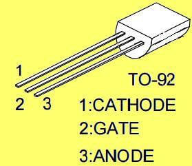
  • To tum on a thyristor, a low voltage, short duration pulse is applied to the gate (typically 4V, 100µs).
  • Once the thyristor is turned-on, the gate loses control and the thyristor will only turn off when the load current falls virtually to zero, or the thyristor is reverse biased.
  • The thyristor will turn off naturally with a.c. supplies as the voltage reverses (which is called as Natural Commutation), but no such reversal occurs with d.c. supplies and it is necessary to force a voltage reversal if tum-off is to occur. This process is called Forced Commutation. This post will give you a brief introduction about SCR commutation.

VI characteristics of SCR

Commutation:

The process of turning OFF SCR is defined as “Commutation”.

  • In all commutation techniques, a reverse voltage is applied across the thyristor during the turn OFF process.
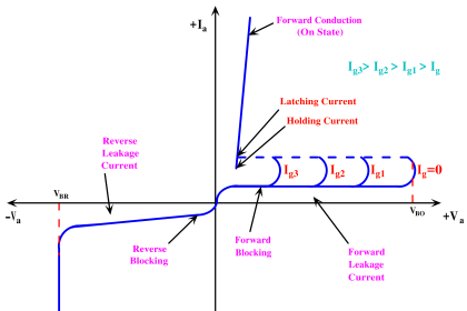
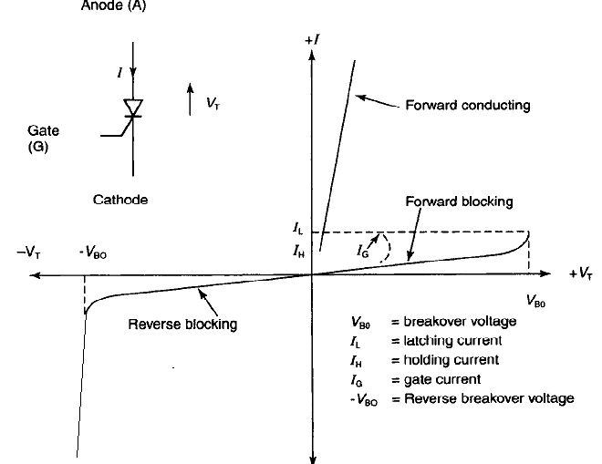
  • By turning OFF a thyristor we bring it from forward conducting to the forward blocking mode.
  • The condition to be satisfied in order to turn OFF an SCR are:
    1. IA < IH ( Anode current must be less than holding current)
    2. A reverse voltage is applied to SCR for sufficient time enabling it to recover its blocking state.
  • There are two methods by which a thyristor can be turned OFF.
    1. Natural Commutation
    2. Forced Commutation

Natural Commutation:-

  • In AC circuit, the current always passes through zero for every half cycle.
  • As the current passes through natural zero, a reverse Voltage will simultaneously appear across the device.
  • This will turn OFF the device immediately.
  • This process is called as natural commutation, since no external circuit is required for this purpose.

Forced Commutation:

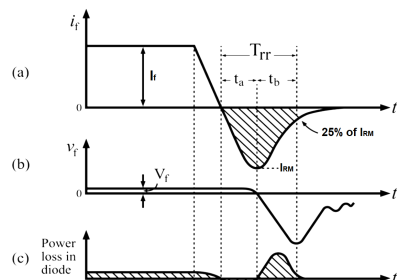
  • To turn OFF a thyristor, the forward anode current should be brought to zero for sufficient time to allow the removal of charged carriers.
  • In case of DC circuits the forward current should be forced to zero by means of some external circuits.
  • This process is called as forced commutation
Don't Miss Our Updates
Be the first to get exclusive content straight to your email.
We promise not to spam you. You can unsubscribe at any time.
Invalid email address
You've successfully subscribed !

Continue Reading

Single-Phase Mid-Point Converter – Bridge Rectifier with Center Tap
How to Test TRIAC with Multimeter
Power Transistor – Structure, Biasing, Characteristics, Advantages
Power Electronic Devices Specification and Classification
R R-C Firing Circuits Disadvantages
Basics of Thyristor
Share This Article
Facebook Whatsapp Whatsapp LinkedIn Copy Link
Share
Leave a Comment

Leave a Reply Cancel reply

Your email address will not be published. Required fields are marked *

Stay Connected

128.3kFollowersLike
69.1kFollowersFollow
210kSubscribersSubscribe
38kFollowersFollow

Categories

Explore More

Power MOSFET – Symbol, Types, Working, Characteristics, Advantages
Thyristor Commutation Techniques – Types, Working Principles
Power Electronics Objective Questions
What is Power Electronics? Evolution, Block Diagram, Advantages
Types of IGBT
IGBT – Symbol, Construction, Working, Characteristics, Advantages
Thyristor Protection Circuits (SCR) – Types, Principle, Explanation
Power Diode – Characteristics, Construction, Working, Advantages

Keep Learning

Thyristor Interview Questions & Answers

Thyristor Interview Questions & Answers

SCR Full Bridge Converter

Power Electronics – Full-wave Rectifier With R and RL Load

RC snubber circuits

How Snubber Circuit works ?

Silicon-Controlled Rectifier (SCR)

Introduction to Thyristor – History, Types, Principle, Advantages

Resistance firing of an SCR in a half-wave circuit

Thyristor Triggering Circuits – Types, Explanation, Waveforms (SCR)

Crowbar fault protection circuit

Crowbar fault protection circuit

Half-controlled Rectifier With R Load

Phase Controlled Rectifier – Half Controlled Rectifier with R Load

RC Triggering

SCR Triggering Methods

Learn More

Vibration Probe Commissioning Checklist

Vibration Probe Commissioning Checklist

Power Electronics Interview Questions & Answers

Power Electronics Interview Questions & Answers

Difference between Accuracy, Tolerance, Uncertainty, and Error

Difference between Accuracy, Tolerance, Uncertainty, and Error

Capacitive Tank Gauges

Capacitive Tank Gauges

ON and OFF a Group of Outputs by One Push button PLC Logic

ON and OFF a Group of Outputs by One Push button PLC Logic

Control Valve with Positioner

 Control Valve Accessories – Principle, Purpose, Advantages

Configuration of Siemens VFD Using TIA Portal

Configuration of Siemens VFD Using TIA Portal Start drive

PLC Program for Car Parking

PLC Program for Entry and Exit Control of Car Parking

Menu

  • About
  • Privacy Policy
  • Copyright

Quick Links

  • Learn PLC
  • Helping Hand
  • Part Time Job

YouTube Subscribe

Follow US
All rights reserved. Reproduction in whole or in part without written permission is prohibited.
Welcome Back!

Sign in to your account

Username or Email Address
Password

Lost your password?